Страница:
Администрация порта Нью-Йорка и Нью-Джерси подписала 26 апреля 2001 года сделку с фирмой Westfield America, ведомую Silverstein. Westfield America взяла в аренду залы, а [Larry] Silverstein офисную часть.
Сделка была завершена и отпразднована 23 июля — всего за семь недель до того, как практически весь комплекс был разрушен. Чиновники администрации порта выдали огромный набор ключей от комплекса в руки Silverstein и Lowy, исполнительного директора компании Westfield.
Silverstein был тогда в восторге. «Это сбывшаяся мечта, — говорил он. — Мы будем управлять ценнейшим владением, и мы будем искать пути развития его потенциала, подняв его до новых высот». Занятный подбор слов, если смотреть с нынешних позиций. — The Blockbuster
«Спорные достаточные основания» обеспечили удары самолетов и последующие структурные повреждения и пожар. Следовательно, согласно такому сценарию, целью атак не было непосредственное разрушение Башен-Близнецов, но скорее, обеспечение «оправдания» подрыву взрывчатки, которая снесла здания в ходе контролируемого обрушения.
Будет любопытным, рассматривая эту версию, обратить внимание на промежуток времени, в течение которого Башни-Близнецы стояли после самолетных таранов. Как замечено выше, в Северную Башню самолет врезался в 8:45 утра, под прямым углом и большая часть авиатоплива попала внутрь здания, вызвав сильнейший пожар. Затем в 9:03 утра был нанесен удар по Южной Башне, но самолет врезался в башню под острым углом, и сравнительно небольшая часть топлива попала внутрь, в основном сгорев снаружи. В обоих случаях пожар внутри потух через некоторое время, шел только густой черный дым. Если Башни-Близнеца были намеренно разрушены, и имелось намерение обвинить в обрушении пожары (согласно официальной версии) то самое позднее, когда башни нужно было обрушить — это когда пожар начал потухать. Т.к. пожар в Южной Башне был вызван меньшим количеством горючего, чем в Северной, он погас раньше. Те, кто управлял разрушением вынуждены были обрушить Южную Башню раньше Северной. Действительно, Южная Башня обрушилась в 9:59 утра, через 56 минут после столкновения, тогда как Северная — в 10:29 утра, через 1 час и 44 минуты после удара. Это время согласуется с версией, что за пожарами наблюдали те, кто контролировал разрушение, и что они обрушили здания в самый последний момент, как раз когда огонь стал гаснуть.
Где потеряли 32.000 тонн стали?
The World Trade Center demolition
The author of this article is unknown. It is one of many articles, mostly concerning 9/11, which appeared anonymously during 2002-2003 at nerdcities.com/guardian/. The website disappeared in April 2003, but is preserved at http://thewebfairy.com/nerdcities/.
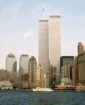
On the 11th September, 2001, three steel framed skyscrapers, World Trade Center One, World Trade Center Two and World Trade Center Seven, collapsed entirely. Other than structures bought down in controlled demolitions, these three buildings are the only steel framed skyscrapers, in the entire history of high rise buildings, to have suffered total collapse. World Trade Centers 3, 4, 5 and 6 also suffered significant damage, but none of these suffered the total collapse seen in World Trade Centers 1, 2 and 7 (in fact, these other buildings showed amazing survivability given that they were repeatedly hit by hundreds of tons of pieces of World Trade Centers 1 and 2, which on impact were traveling at well over 100 miles per hour). On the 23rd July, 2001, just seven weeks previous, the Port Authority of New York and New Jersey signed a deal with a consortium led by Larry Silverstein for a 99 year lease of the World Trade Center complex. The leased buildings included WTCs One, Two, Four, Five and 400,000 square feet of retail space. The Marriott Hotel (WTC 3), U.S. Customs building (WTC 6) and Silverstein's own 47-story office building (WTC 7) were already under lease. Silverstein is seeking $7.2 billion from insurers for the destruction of the center. One would estimate that the chances of the insurers paying out anything at all, are close to zero. It should be emphasized that World Trade Center Seven suffered total collapse. World Trade Center Seven was neither hit by an aircraft nor by falling debris from the twin towers. If the claim that it was destroyed by fire were true (it is not) then it would be the only steel framed skyscraper ever to have collapsed exclusively due to fire. Although the WTC Seven collapse warrants the writing of a book, we will deal only with the collapses of WTCs One and Two.
On the 11th September, 2001, three steel framed skyscrapers, World Trade Center One, World Trade Center Two and World Trade Center Seven, collapsed entirely. Other than structures bought down in controlled demolitions, these three buildings are the only steel framed skyscrapers, in the entire history of high rise buildings, to have suffered total collapse. World Trade Centers 3, 4, 5 and 6 also suffered significant damage, but none of these suffered the total collapse seen in World Trade Centers 1, 2 and 7 (in fact, these other buildings showed amazing survivability given that they were repeatedly hit by hundreds of tons of pieces of World Trade Centers 1 and 2, which on impact were traveling at well over 100 miles per hour). On the 23rd July, 2001, just seven weeks previous, the Port Authority of New York and New Jersey signed a deal with a consortium led by Larry Silverstein for a 99 year lease of the World Trade Center complex. The leased buildings included WTCs One, Two, Four, Five and 400,000 square feet of retail space. The Marriott Hotel (WTC 3), U.S. Customs building (WTC 6) and Silverstein's own 47-story office building (WTC 7) were already under lease. Silverstein is seeking $7.2 billion from insurers for the destruction of the center. One would estimate that the chances of the insurers paying out anything at all, are close to zero. It should be emphasized that World Trade Center Seven suffered total collapse. World Trade Center Seven was neither hit by an aircraft nor by falling debris from the twin towers. If the claim that it was destroyed by fire were true (it is not) then it would be the only steel framed skyscraper ever to have collapsed exclusively due to fire. Although the WTC Seven collapse warrants the writing of a book, we will deal only with the collapses of WTCs One and Two.
The WTC was designed to survive the impact of a Boeing 767
Fact. The twin towers were designed to withstand a collision with a Boeing 707.
The maximum takeoff weight for a Boeing 707-320B is 336,000 pounds.
The maximum takeoff weight for a Boeing 767-200ER is 395,000 pounds.
The wingspan of a Boeing 707 is 146 feet.
The wingspan of a Boeing 767 is 156 feet.
The length of a Boeing 707 is 153 feet.
The length of a Boeing 767 is 159 feet.
The Boeing 707 could carry 23,000 gallons of fuel.
The Boeing 767 could carry 23,980 gallons of fuel.
The cruise speed of a Boeing 707 is 607 mph = 890 ft/s,
The cruise speed of a Boeing 767 is 530 mph = 777 ft/s.
So, the Boeing 707 and 767 are very similar aircraft, with the main differences being that the 767 is slightly heavier and the 707 is faster.
In designing the towers to withstand the impact of a Boeing 707, the designers would have assumed that the aircraft was operated normally. So they would have assumed that the aircraft was traveling at its cruise speed and not at the break neck speed of some kamikaze. With this in mind, we can calculate the energy that the plane would impart to the towers in any accidental collision.
The kinetic energy released by the impact of a Boeing 707 at cruise speed is
= 0.5 x 336,000 x (890)^2/32.174 = 4.136 billion ft lbs force (5,607,720 Kilojoules).
The kinetic energy released by the impact of a Boeing 767 at cruise speed is
= 0.5 x 395,000 x (777)^2/32.174 = 3.706 billion ft lbs force (5,024,650 Kilojoules).
From this, we see that under normal flying conditions, a Boeing 707 would smash into the WTC with about 10 percent more energy than would the slightly heavier Boeing 767. That is, under normal flying conditions, a Boeing 707 would do more damage than a Boeing 767.
In conclusion we can say that if the towers were designed to survive the impact of a Boeing 707, then they were necessarily designed to survive the impact of a Boeing 767.
So what can be said about the actual impacts?
The speed of impact of AA Flight 11 was 470 mph = 689 ft/s.
The speed of impact of UA Flight 175 was 590 mph = 865 ft/s.
The kinetic energy released by the impact of AA Flight 11 was
= 0.5 x 395,000 x (689)^2/32.174 = 2.914 billion ft lbs force (3,950,950 Kilojoules).
This is well within limits that the towers were built to survive. So why did the North tower fall?
The kinetic energy released by the impact of UA Flight 175 was
= 0.5 x 395,000 x (865)^2/32.174 = 4.593 billion ft lbs force (6,227,270 Kilojoules).
This is within 10 percent of the energy released by the impact of a Boeing 707 at cruise speed. So, it is also a surprise that the 767 impact caused the South tower to fall.
Overall, it comes as a great surprise that the impact of a Boeing 767 bought down either tower. Indeed, many experts are on record as saying that the towers would survive the impact of the larger and faster Boeing 747. In this regard, see professor Astaneh-Asl's simulation of the crash of the much, much larger and heavier Boeing 747 with the World Trade Center. Professor Astaneh-Asl teaches at the University of California, Berkeley.
Although the jet fuel fires have been ruled out as the cause of the collapses, it should still be pointed out that the fuel capacities of the Boeing 707 and the Boeing 767 are essentially the same. And in any case, it has been estimated that both UA Flight 175 and AA Flight 11 were carrying about 10,000 gallons of fuel when they impacted. This is well below the 23,000 gallon capacity of a Boeing 707 or 767. Thus the amount of fuel that exploded and burnt on September 11 was envisaged by those who designed the towers. Consequently, the towers were designed to survive such fires. It should also be mentioned that other high-rise buildings have suffered significantly more serious fires than those of the twin towers on September 11, and did not collapse.
The «Truss theory» is ludicrous
The truss theory is the absurd belief that the only support (between the central core and the perimeter wall) for the concrete floor slabs, was lightweight trusses. It was invented to explain away what were obviously demolitions and has become the «official» dogma. The central core, perimeter wall and the mythical trusses are all introduced in the next section. There you will find out their dimensions, their numbers and their supposed usage. After reading the rest of this article you should return to this section and (with improved understanding) read it again.
According to the «official» story, there is no significant lateral support for the walls (against wind loading) between the ground and top floors. This is like a bridge with a 1,300 foot span between supports. Even though the tube structure of the perimeter wall was designed for maximum rigidity (within the given weight specifications) the 1,300 foot span between supporting pillars, meant that even this very rigid design would sag in the midsection under wind loading, just like a bridge with such a span. In a typical steel framed building the span between pillars is only 12 feet (one floor) and such a problem does not arise.
The World Trade Center towers were like huge sails in the wind. These sails had to be able to resist the 140 mile per hour winds of a hurricane. Such hurricane force winds exerted a large (some 6000 tons) lateral force on the building. This lateral force is called the wind loading (or force of the wind) on the building. According to the «official» story, the only possible intermediate support comes from the flimsy trusses and the lightweight concrete floors. The WTC was designed to survive a 45 pounds per square foot, wind loading. This translates to a 12 x 207 x 45/2000 = 56 ton force on each of the floor segments. What this 56 ton force on each floor segment means, is that if one was to lay the World Trade Center on its side and use the pull of gravity as a substitute for the push of the wind, then each of the 110 floors would need to be loaded with a 56 ton block of steel (so the entire wall would have to support 110 such blocks of steel, that is, 110 x 56 = 6160 tons in total).
The fact that the tubular structure of the walls is very rigid, does not stop the central core from needing to bend when the walls bend. This means that the walls have to transmit the full force of the wind to the core, so that the core will flex to the same extent as the walls (this is obvious, otherwise if the walls flex while the core does not, the floor slabs would, by definition, be crushed). Again, it is important to note that the rigidity of the walls does not protect the central core from the full force of the wind, what it does, is it limits the distance that the walls (and hence the whole structure) can bend. The more rigid the design the less it tilts in the wind.
In strong winds the midsection of the windward wall will be pushed several feet towards the core. In a typical steel framed building of WTC type design, heavy steel beams transmit the wind loading to the core, which then bends together with the walls. However, in the WTC (as described in the «truss theory») the trusses and floor slabs are too weak to transmit this force to the core without buckling, so the core will stay in its original position as the wall advances to it. This will crush the trusses and floor slabs, leading to the collapse of many floors. Since this did not occur during the 30 years in which the buildings stood, we must assume that the «official» story is false. To see how utterly ridiculous the «official» story is, lets calculate the lateral loading (wind loading) that each one of these trusses was expected to resist. Consider, a one floor segment. Here, we have 30 trusses and a slab of concrete supporting 56 tons. That is about 2 tons per truss and piece of slab. If you balanced a 2 ton block of steel on top of one of these flimsy 60 foot long trusses and (a 60 foot long by 6 foot 8 inches wide by 4 inches thick) slab of concrete, we all know what would happen — the truss and slab would buckle and collapse.
Another point to consider, is that if the walls alone handle lateral loading, then the pressure on the windward wall must be transmitted via the corners to the remaining walls (this transmission of loading to the other walls is what gave the WTC its rigidity) but corners are far too weak to handle this task alone.
Although the «truss theory» is ludicrous, it has been pushed by many «experts». It should be noted that it is inconceivable that these experts did not know that it was false.
Where is the steel?
Since the trusses are incapable of resisting the wind loading, we know that the «official» explanation of the WTC collapse is false. If the floor joists (supports) were not the claimed trusses, then what were they? They had to be strong enough to support the floor slab and stiff enough to resist the wind loading. In fact, they had to be large steel beams. This is not to say that trusses were not used at all in the construction, but just that (contrary to the «official» line) the main floor joists were steel beams and not trusses.
The above argument using wind loading is certainly enough to tell one that trusses were not really used as the floor joists, but there are also other ways to determine this. Another approach is adopted in this section. We will:
• Calculate the weight of steel theoretically used in the construction of one of the towers assuming that the floor joists were trusses.
• Compare the result of this calculation to the 96,000 tons of steel known to have been used in the construction of each of the towers.
• Note that the calculated weight of steel is only 67 percent of the required 96,000 tons.
• Conclude that the 32,000 tons of steel unaccounted for, is due to the fact the the floor joists were actually weighty steel beams and not flimsy trusses (and thus that the official story is a lie spun to explain away what were obviously demolitions).
• Calculate a rough cross-sectional area for the steel beams that did serve as floor joists.
Since a cubic foot of steel weights 490 pounds, it is enough to deal with volumes rather than weights. We will calculate the volume of steel on a per floor basis.
To calculate the per floor volume of steel used in the construction of the twin towers, we will divide the calculation into three parts, namely, the volume of steel in the perimeter wall, the volume in the central core and the volume used in the floor support system.
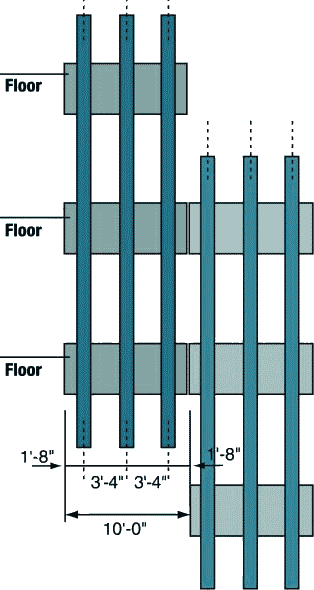
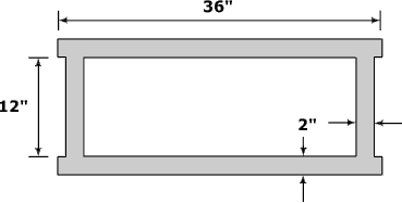
The perimeter wall was comprised of box columns welded to large spandrel plates. Two typical prefabricated sections are illustrated below. Each consists of three spandrel plates welded to three box columns and each is three floors high.
The first figure below shows the cross section of one of the perimeter box columns and its surrounds. The second and third figures detail the dimensions of two actual perimeter columns that were salvaged from the rubble.
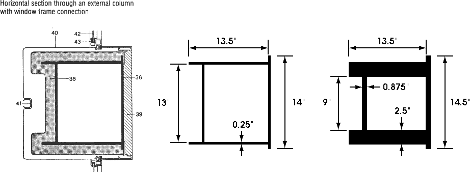
The numbers in the figure denote:
• 36 — the steel column
• 38 and 39 — fire resistant plaster
• 40 — aluminum facade
• 42 — window glass
• 43 — the window frame.
To obtain an estimate of the «typical» perimeter column, the dimensions of the perimeter columns listed in the WTC Steel Data Collection documentation were averaged. Whether this accurately reflects the true distribution of perimeter column thickness, is unclear, but it is all one has to go on (till those who hold the architectural details release them).
So, our «average» perimeter column has dimensions:
d = 13.4, t_w = 0.48, b_f = 12.9, t_(tf) = 0.32 and t_(bf) = 0.32.
and cross-sectional area:
2 x (13.4 x 0.48) + (12.9 x 0.32) + (14 x 0.32) = 21.5 square inches,
The parameters d, t_w, b_f, t_(tf) and t_(bf) are as in the following diagram from Appendix D which is part of the report found at http://www.house.gov/science/hot/wtc/wtcreport.htm.

For the time being we will ignore the column end plates and the spandrel beams. Since each floor is 12 feet high, the per floor volume of steel in an average perimeter box column is:
12 x 21.5/144 = 1.792 cubic feet.
In total there are 240 such columns, so the volume of steel so far is
240 x 1.792 = 430 cubic feet.
Now lets deal with the volume of steel in the column end plates. Each end plate is 14 inches wide by 11.75 inches deep and 1.375 inches thick, giving a volume of
14 x 11.75 x 1.375 = 226.2 cubic inches = 226.2/1728 = 0.130896 cubic feet.
Since, on each floor, one third of the columns are joined, and each join involves two end plates, the per floor volume of steel in the end plates is
2 x 0.130896 x 240/3 = 20.9433 cubic feet.
The spandrel plates are large, being 52 inches high and 3/8 inches thick. Each floor has the equivalent of one spandrel beam that stretches 4 x 207 = 828 feet right around the building. The volume is easily calculated to be
828 x 12 x 52 x 3/8 = 193752 cubic inches = 193752/1728 = 112.125 cubic feet.
So the overall per floor volume of steel in the perimeter wall is
430 + 21 + 112 = 563 cubic feet.
Now, we wish to calculate the per floor volume of steel in the core section of the building. To do this, we first need to calculate the volume of steel in each of the core columns. This is complicated by the fact that the dimensions of the columns reduced in size with increasing height. For example, at the base of the WTC some of these columns were 36 inches wide by 16 inches deep and 4 inches thick, whereas at the top, these box columns had transitioned to H-sections (I-sections) fabricated from 3/4 inch steel (the transition to H-sections occurred at floor 85). We will ignore the reduction in width and breadth of the columns, and only take into account the reduction in column thickness by assuming an average thickness of 2 inches (this roughly corresponds to a reduction in thickness of one quarter of an inch, every seven floors, up to floor 85). In reality, the column width and breadth decreased quite considerably and we only make this very generous assumption as the actual reductions in the width and breadth are unknown. So, we assume each core column has the following cross-section:
The cross-sectional area is (36 + 12 + 36 + 12) x 2 = 192 square inches = 192/144 = 1.333 square feet. Since each floor is 12 foot high, the per floor volume of steel in one such column is 12 x 1.333 = 16 cubic feet. Reports as to the number of core columns vary from 44 to 47. Once again, we will be generous in our assumptions and choose the higher figure of 47. Thus, the total volume of steel (per floor) in the core columns is
47 x 16 = 752 cubic feet.
On each floor, the core columns were bound together by a rectangular grid of beams. As the dimensions of these beams are not known we will assume they were, 14 inch by 14 inch box sections fabricated from 3/4 inch steel. Again, this is a very generous assumption. The cross-sectional area of such a box section is:
( 2 x 14 x 0.75 ) + ( 2 x 12.5 x 0.75 ) = 39.75 square inches = 39.75/144 = 0.276 square feet.
The core section is 137 feet wide x 87 feet deep. Hence, our rectangular grid comprises six 137 foot sections and eight 87 foot sections, for a total length of 822 + 696 = 1518 feet. Additionally, the outer two 137 foot sections have to extend to the perimeter wall (to give support for the trusses). Actually, the «official» version has a much smaller U shaped beam, but as I have mentioned above, we are being very generous. This adds another 140 feet to the length. The volume of the 1518 + 140 = 1658 feet of box section is:
1658 x 0.276 = 458 cubic feet.
Thus the overall volume of steel in the core section is:
752 + 458 = 1210 cubic feet.
We now turn our attention to the floor support system.
The floor slab was poured on 1.5 inch corrugated 22-gauge steel decking. Now, 22-gauge steel is 0.0336 of an inch thick. The corrugations lead to 1.25 square feet of steel decking for every square feet of floor slab. Hence, the volume of steel involved is:
207 x 207 x 1.25 x 0.0336/12 = 150 cubic feet.
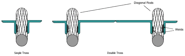
To complete our calculations, we need to calculate the volume of steel used in the system of trusses which supposedly supported the concrete floor slabs. The following graphic illustrates the truss system. The double trusses (of which, in this graphic, we only have an end view) ran perpendicular to the transverse trusses, and were essentially two transverse trusses bound together.
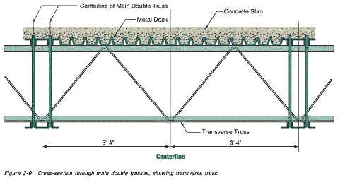
Consider one of the 3 foot four inch (40 inch) sections illustrated in the above graphic. The diagonal rod has a diameter of 1.09 inches (radius 0.545 inches) and a length of twice the square root of 20 squared plus 30 squared, that is, a length of
2 x srt( 20^2 + 30^2 ) = 2 x srt( 1300 ) = 72 inches.
Here, srt stands for the square root.
The cross-sectional area of the rod is 3.14 x 0.545 x 0.545 = 0.933 square inches. Hence the volume of rod in this segment is 72 x 0.933 = 67.2 cubic inches.
This gives a volume of 67.2 x 12/40 = 20.16 cubic inches per foot of truss.
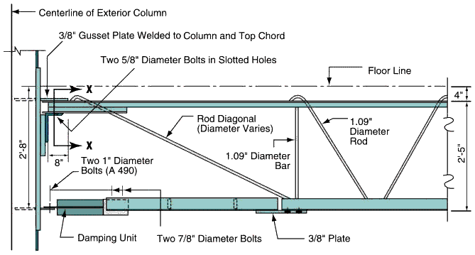
Pictured above, is the connection of one of the double trusses to the perimeter wall. The cross section marked X—X in this graphic, is pictured below. Note that the original graphic from the WTC-report was so out of scale, that it was necessary to stretch it somewhat.

The first image below is apparently the real life version of the above graphic (supposedly obtained from the WTC wreckage). The second image shows the gusset plate and seat connection.
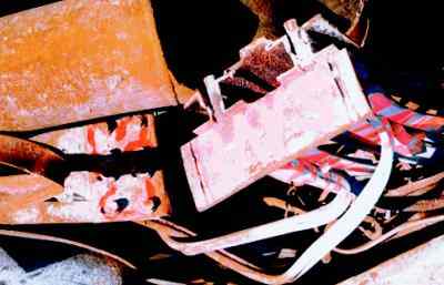
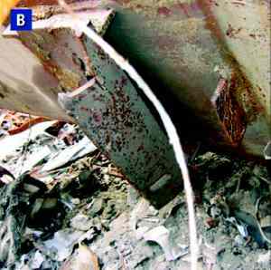
The dimensions quoted in the following section were made by taking measurements from these two photos. Standard adjustments for perspective had to be made for measurements from the second photo.
The gusset plate is 4 x 2 x 3/8 and has a volume of 3 cubic inches. The seat angle has a volume of roughly 2 x ((9 + 4) x 14.5 x 3/8) = 141 cubic inches and the «stiffeners» add another 9 x 1.5 x 3/8 = 5 cubic inches. Since there were (at most) 120 gusset plates and seat angles, these add in 120 x 149 = 17880 cubic inches. The 76 horizontal diagonal brace plates add in another 76 x 90 x 3/2 x 1/2 = 5130 cubic inches for an addition of (17880 + 5130)/1728 = 13.3 cubic feet of steel to our total.
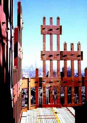
The upper chord (top section) of one of the double trusses consisted of four pieces of 1/8 inch thick angle iron, as illustrated below (it is circled in red).

Below, is a more detailed view of the cross section of the top chord of a transverse truss (left) and double truss (right).
So, the upper chord has a cross sectional area of
((2 + 1.25) + (1.25 + 2))/8 = 0.8125 square inches for a transverse truss and,
((2 + 1.25) + (1.25 + 7 + 1.25) + (1.25 + 2))/8 = 2 square inches for a double truss.
Since we have no information concerning the lower chord (and the «official» pictures are inconsistent and nowhere near to scale) we will assume it has the same dimensions as the upper chord.
Now summing the volume of steel in the top and bottom chords and diagonal rods, we have the following per foot volumes:
2 x 0.8125 x 12 + 20.16 = 39.7 cubic inches per foot for the transverse trusses, and
2 x 2 x 12 + 2 x 20.16 = 88.3 cubic inches per foot for the double trusses.
Now we need to calculate the total length of double and transverse trussing. There were apparently, 60 double trusses spanning the 60 feet from the perimeter wall to (a beam attached to) the core and 24 double trusses spanning the 35 feet from the perimeter wall to the core. They are pictured in the following graphic:
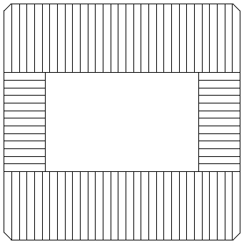
The overall length of double trussing was thus 60 x 60 + 24 x 35 = 4440 feet. Transverse trusses ran perpendicular to the double trusses as illustrated:
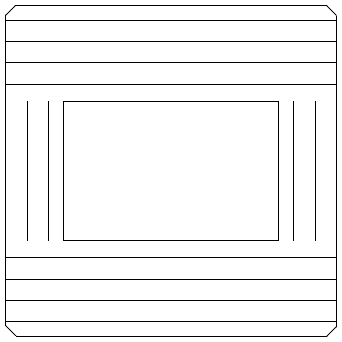
The overall length of transverse trussing was thus 8 x 207 + 4 x 87 = 2004 feet.
There was also a lesser supporting feature called «intermediate support angle». Since all we know about the intermediate support angle, is that its support capabilities were inferior to the double and transverse trusses, we shall be generous and assume that it was similar in nature to the transverse trusses. This adds another 1764 feet, to give a total of 2004 + 1764 = 3768 feet of transverse trussing.
Hence, the volume of steel in the double trusses was 4440 x 88.3/1728 = 227 cubic feet.
And the volume of steel in the transverse trusses was 3768 x 39.7/1728 = 86.6 cubic feet.
So the overall per floor volume of steel in the floor support system was
150 + 13.3 + 227 + 86.6 = 477 cubic feet.
The total per floor volume of steel, is now the sum of that in the perimeter wall, the central core section and the floor system. This is 563 + 1210 + 477 = 2250 cubic feet.
So why have we gone to all this trouble to calculate the per floor volume of steel? Well, we know that 96,000 tons of steel was used in the construction of each of the WTC towers. The WTC towers had 117 floors (110 above and 7 below the Plaza level) so an average floor contained 96,000/117 = 820 tons of steel. Since the density of steel is 490 pounds per cubic foot, we see that each floor contained about 820 x 2000/490 = 3347 cubic feet of steel.
Now, according to the above calculations, the per floor volume of steel in each of the towers, is (a very generous) 2250 cubic feet. But this is only 67 percent of the volume of steel that we know was used in the construction of the tower. So, the big question is: Where is the other 33 percent? Where are the missing 32,000 tons of steel? What features of the building are being left out of the «official» explanations?
Could it be that each concrete floor was actually supported by weighty steel beams and not by the very flimsy trusses of the «official» story?
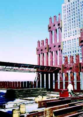
Well, the following picture, taken during the construction of the WTC, may hold the answer.
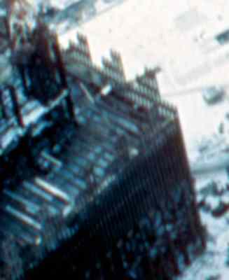
Here, one can see what appear to be large steel girders laid out according to the plan for the positioning of the supposed double trusses (this plan is pictured here). To make things clearer, the position of the girders have been marked in white in the photo below. Remember, that the perimeter columns which appear like a row of toothpicks in the visible sections of the wall, are actually 14 inches wide. Thus the floor joists do indeed appear to be quite large steel girders. One thing is certain though, they are not the claimed double trusses.
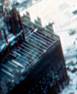
In this photo the vertical red lines correspond to visible core columns. The white lines (apart from the outer perimeter lines) correspond to visible floor joists.
Above, is a photo of early construction work on the South Tower. Behind, is the North Tower and further back, the Verizon building. The photo was taken from the old extention of Greenwich Street (which was ripped up to make way for WTCs 4 and 5) looking north west. Some interesting aspects of the construction are presented in the following enlargements of the red-boxed regions.
In this enlargement one can see eight perimeter box columns at ten foot intervals (further up the structure these columns split into three smaller box columns at 40 inch intervals). Of course, what is of interest here are the eight (seven on the lower level and one on the upper) quite solid looking beams spanning the 35 foot gap between the perimeter wall and the central core, where the «official line» promised us there were only flimsy trusses.
In the foreground of this enlargement one can see eighteen perimeter box columns of the South Tower (those in the background are of the North Tower). If you look closely, you can just make out a single quite large beam spanning the 60 foot gap between the central core and the perimeter wall. Remember, that the corner core column to which this beam is attached is some 3 foot wide (and 16 inches deep). However, one floor below this, workers are working on a section of flooring held up by what appears to be trussing. One supposes that this is temporary flooring. If one looks carefully one can see a barrier rail to prevent workers from falling off the area supported by the trusses. This tends to support the case that this is temporary flooring.
Assuming that all the missing steel is contained in these beams we can estimate their cross-sectional area (the assumption that all the missing steel is contained in these beams is somewhat dubious, as I suspect that the sample of perimeter columns has been deliberately biased toward columns with thin cross-sections, and hence, that a significant percentage of the missing steel, is missing from the perimeter columns). Still, using this assumption, we have 1100 + 227 = 1327 cubic feet of steel to play with (the 227 comes from the no longer necessary double trussing). The total length of double trussing to be replaced is 4440 feet. Hence, the desired estimate of the cross-sectional area is:
1327/4440 x 144 = 43 square inches.
So, we have enough steel to replace the double trusses by H-beams (or I-beams, depending on how you view them) that are 24 inches deep, 10 inches wide and fabricated from one inch thick steel. These would be very, very strong beams, and would be much, much stronger than necessary to span the 35 and 60 foot spans from the central core to the perimeter wall.
It is worth emphasizing that these beams, plus the thicker stronger perimeter columns, would mean that WTC One and Two were actually traditional steel-framed buildings, that also incorporated extra thinner perimeter columns, to attain the rigidity necessary to resist wind loading.
Above are pictures taken during the construction of the WTC. On the right is a picture of some 30 feet of trussing, which one supposes was temporary flooring. Note the vertical gaps in the box columns of the perimeter wall. Gaps in the box columns do not seem to be a sensible feature in a supposedly load bearing wall. Is this because the perimeter wall was not actually meant to be a load bearing wall as such, but a feature designed to give the WTC its required rigidity (against wind loading)? In the left photo note the yellow and red lines in the concrete. In the right photo note the three parallel light-colored lines (about 4 inches wide) in the concrete. One also wonders why the pile of steel in the foreground was hoisted up the building, unless it was to be incorporated in the structure. An answer to this question may be provided by the following photo.
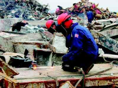
Between the workers cutting up a couple of WTC core columns, is a column with concrete still attached to the beams that are welded/bolted to it. These U-shaped beams look suspiciously like the lengths of steel in the foreground of the picture of the trussing. Is it possible that floor slab was some eight inches thick and laced with significant steel beams? Was the slab poured in situ and not prefabricated as some claim? Was the temporary flooring only necessary till the concrete in the floor slabs had set? And where does the following piece fit in the whole affair?
The above argument using wind loading is certainly enough to tell one that trusses were not really used as the floor joists, but there are also other ways to determine this. Another approach is adopted in this section. We will:
• Calculate the weight of steel theoretically used in the construction of one of the towers assuming that the floor joists were trusses.
• Compare the result of this calculation to the 96,000 tons of steel known to have been used in the construction of each of the towers.
• Note that the calculated weight of steel is only 67 percent of the required 96,000 tons.
• Conclude that the 32,000 tons of steel unaccounted for, is due to the fact the the floor joists were actually weighty steel beams and not flimsy trusses (and thus that the official story is a lie spun to explain away what were obviously demolitions).
• Calculate a rough cross-sectional area for the steel beams that did serve as floor joists.
Since a cubic foot of steel weights 490 pounds, it is enough to deal with volumes rather than weights. We will calculate the volume of steel on a per floor basis.
To calculate the per floor volume of steel used in the construction of the twin towers, we will divide the calculation into three parts, namely, the volume of steel in the perimeter wall, the volume in the central core and the volume used in the floor support system.
The perimeter wall was comprised of box columns welded to large spandrel plates. Two typical prefabricated sections are illustrated below. Each consists of three spandrel plates welded to three box columns and each is three floors high.
The first figure below shows the cross section of one of the perimeter box columns and its surrounds. The second and third figures detail the dimensions of two actual perimeter columns that were salvaged from the rubble.
The numbers in the figure denote:
• 36 — the steel column
• 38 and 39 — fire resistant plaster
• 40 — aluminum facade
• 42 — window glass
• 43 — the window frame.
To obtain an estimate of the «typical» perimeter column, the dimensions of the perimeter columns listed in the WTC Steel Data Collection documentation were averaged. Whether this accurately reflects the true distribution of perimeter column thickness, is unclear, but it is all one has to go on (till those who hold the architectural details release them).
So, our «average» perimeter column has dimensions:
d = 13.4, t_w = 0.48, b_f = 12.9, t_(tf) = 0.32 and t_(bf) = 0.32.
and cross-sectional area:
2 x (13.4 x 0.48) + (12.9 x 0.32) + (14 x 0.32) = 21.5 square inches,
The parameters d, t_w, b_f, t_(tf) and t_(bf) are as in the following diagram from Appendix D which is part of the report found at http://www.house.gov/science/hot/wtc/wtcreport.htm.
For the time being we will ignore the column end plates and the spandrel beams. Since each floor is 12 feet high, the per floor volume of steel in an average perimeter box column is:
12 x 21.5/144 = 1.792 cubic feet.
In total there are 240 such columns, so the volume of steel so far is
240 x 1.792 = 430 cubic feet.
Now lets deal with the volume of steel in the column end plates. Each end plate is 14 inches wide by 11.75 inches deep and 1.375 inches thick, giving a volume of
14 x 11.75 x 1.375 = 226.2 cubic inches = 226.2/1728 = 0.130896 cubic feet.
Since, on each floor, one third of the columns are joined, and each join involves two end plates, the per floor volume of steel in the end plates is
2 x 0.130896 x 240/3 = 20.9433 cubic feet.
The spandrel plates are large, being 52 inches high and 3/8 inches thick. Each floor has the equivalent of one spandrel beam that stretches 4 x 207 = 828 feet right around the building. The volume is easily calculated to be
828 x 12 x 52 x 3/8 = 193752 cubic inches = 193752/1728 = 112.125 cubic feet.
So the overall per floor volume of steel in the perimeter wall is
430 + 21 + 112 = 563 cubic feet.
Now, we wish to calculate the per floor volume of steel in the core section of the building. To do this, we first need to calculate the volume of steel in each of the core columns. This is complicated by the fact that the dimensions of the columns reduced in size with increasing height. For example, at the base of the WTC some of these columns were 36 inches wide by 16 inches deep and 4 inches thick, whereas at the top, these box columns had transitioned to H-sections (I-sections) fabricated from 3/4 inch steel (the transition to H-sections occurred at floor 85). We will ignore the reduction in width and breadth of the columns, and only take into account the reduction in column thickness by assuming an average thickness of 2 inches (this roughly corresponds to a reduction in thickness of one quarter of an inch, every seven floors, up to floor 85). In reality, the column width and breadth decreased quite considerably and we only make this very generous assumption as the actual reductions in the width and breadth are unknown. So, we assume each core column has the following cross-section:
The cross-sectional area is (36 + 12 + 36 + 12) x 2 = 192 square inches = 192/144 = 1.333 square feet. Since each floor is 12 foot high, the per floor volume of steel in one such column is 12 x 1.333 = 16 cubic feet. Reports as to the number of core columns vary from 44 to 47. Once again, we will be generous in our assumptions and choose the higher figure of 47. Thus, the total volume of steel (per floor) in the core columns is
47 x 16 = 752 cubic feet.
On each floor, the core columns were bound together by a rectangular grid of beams. As the dimensions of these beams are not known we will assume they were, 14 inch by 14 inch box sections fabricated from 3/4 inch steel. Again, this is a very generous assumption. The cross-sectional area of such a box section is:
( 2 x 14 x 0.75 ) + ( 2 x 12.5 x 0.75 ) = 39.75 square inches = 39.75/144 = 0.276 square feet.
The core section is 137 feet wide x 87 feet deep. Hence, our rectangular grid comprises six 137 foot sections and eight 87 foot sections, for a total length of 822 + 696 = 1518 feet. Additionally, the outer two 137 foot sections have to extend to the perimeter wall (to give support for the trusses). Actually, the «official» version has a much smaller U shaped beam, but as I have mentioned above, we are being very generous. This adds another 140 feet to the length. The volume of the 1518 + 140 = 1658 feet of box section is:
1658 x 0.276 = 458 cubic feet.
Thus the overall volume of steel in the core section is:
752 + 458 = 1210 cubic feet.
We now turn our attention to the floor support system.
The floor slab was poured on 1.5 inch corrugated 22-gauge steel decking. Now, 22-gauge steel is 0.0336 of an inch thick. The corrugations lead to 1.25 square feet of steel decking for every square feet of floor slab. Hence, the volume of steel involved is:
207 x 207 x 1.25 x 0.0336/12 = 150 cubic feet.
To complete our calculations, we need to calculate the volume of steel used in the system of trusses which supposedly supported the concrete floor slabs. The following graphic illustrates the truss system. The double trusses (of which, in this graphic, we only have an end view) ran perpendicular to the transverse trusses, and were essentially two transverse trusses bound together.
Consider one of the 3 foot four inch (40 inch) sections illustrated in the above graphic. The diagonal rod has a diameter of 1.09 inches (radius 0.545 inches) and a length of twice the square root of 20 squared plus 30 squared, that is, a length of
2 x srt( 20^2 + 30^2 ) = 2 x srt( 1300 ) = 72 inches.
Here, srt stands for the square root.
The cross-sectional area of the rod is 3.14 x 0.545 x 0.545 = 0.933 square inches. Hence the volume of rod in this segment is 72 x 0.933 = 67.2 cubic inches.
This gives a volume of 67.2 x 12/40 = 20.16 cubic inches per foot of truss.
Pictured above, is the connection of one of the double trusses to the perimeter wall. The cross section marked X—X in this graphic, is pictured below. Note that the original graphic from the WTC-report was so out of scale, that it was necessary to stretch it somewhat.
The first image below is apparently the real life version of the above graphic (supposedly obtained from the WTC wreckage). The second image shows the gusset plate and seat connection.
The dimensions quoted in the following section were made by taking measurements from these two photos. Standard adjustments for perspective had to be made for measurements from the second photo.
The gusset plate is 4 x 2 x 3/8 and has a volume of 3 cubic inches. The seat angle has a volume of roughly 2 x ((9 + 4) x 14.5 x 3/8) = 141 cubic inches and the «stiffeners» add another 9 x 1.5 x 3/8 = 5 cubic inches. Since there were (at most) 120 gusset plates and seat angles, these add in 120 x 149 = 17880 cubic inches. The 76 horizontal diagonal brace plates add in another 76 x 90 x 3/2 x 1/2 = 5130 cubic inches for an addition of (17880 + 5130)/1728 = 13.3 cubic feet of steel to our total.
The upper chord (top section) of one of the double trusses consisted of four pieces of 1/8 inch thick angle iron, as illustrated below (it is circled in red).
Below, is a more detailed view of the cross section of the top chord of a transverse truss (left) and double truss (right).
So, the upper chord has a cross sectional area of
((2 + 1.25) + (1.25 + 2))/8 = 0.8125 square inches for a transverse truss and,
((2 + 1.25) + (1.25 + 7 + 1.25) + (1.25 + 2))/8 = 2 square inches for a double truss.
Since we have no information concerning the lower chord (and the «official» pictures are inconsistent and nowhere near to scale) we will assume it has the same dimensions as the upper chord.
Now summing the volume of steel in the top and bottom chords and diagonal rods, we have the following per foot volumes:
2 x 0.8125 x 12 + 20.16 = 39.7 cubic inches per foot for the transverse trusses, and
2 x 2 x 12 + 2 x 20.16 = 88.3 cubic inches per foot for the double trusses.
Now we need to calculate the total length of double and transverse trussing. There were apparently, 60 double trusses spanning the 60 feet from the perimeter wall to (a beam attached to) the core and 24 double trusses spanning the 35 feet from the perimeter wall to the core. They are pictured in the following graphic:
The overall length of double trussing was thus 60 x 60 + 24 x 35 = 4440 feet. Transverse trusses ran perpendicular to the double trusses as illustrated:
The overall length of transverse trussing was thus 8 x 207 + 4 x 87 = 2004 feet.
There was also a lesser supporting feature called «intermediate support angle». Since all we know about the intermediate support angle, is that its support capabilities were inferior to the double and transverse trusses, we shall be generous and assume that it was similar in nature to the transverse trusses. This adds another 1764 feet, to give a total of 2004 + 1764 = 3768 feet of transverse trussing.
Hence, the volume of steel in the double trusses was 4440 x 88.3/1728 = 227 cubic feet.
And the volume of steel in the transverse trusses was 3768 x 39.7/1728 = 86.6 cubic feet.
So the overall per floor volume of steel in the floor support system was
150 + 13.3 + 227 + 86.6 = 477 cubic feet.
The total per floor volume of steel, is now the sum of that in the perimeter wall, the central core section and the floor system. This is 563 + 1210 + 477 = 2250 cubic feet.
So why have we gone to all this trouble to calculate the per floor volume of steel? Well, we know that 96,000 tons of steel was used in the construction of each of the WTC towers. The WTC towers had 117 floors (110 above and 7 below the Plaza level) so an average floor contained 96,000/117 = 820 tons of steel. Since the density of steel is 490 pounds per cubic foot, we see that each floor contained about 820 x 2000/490 = 3347 cubic feet of steel.
Now, according to the above calculations, the per floor volume of steel in each of the towers, is (a very generous) 2250 cubic feet. But this is only 67 percent of the volume of steel that we know was used in the construction of the tower. So, the big question is: Where is the other 33 percent? Where are the missing 32,000 tons of steel? What features of the building are being left out of the «official» explanations?
Could it be that each concrete floor was actually supported by weighty steel beams and not by the very flimsy trusses of the «official» story?
Well, the following picture, taken during the construction of the WTC, may hold the answer.
Here, one can see what appear to be large steel girders laid out according to the plan for the positioning of the supposed double trusses (this plan is pictured here). To make things clearer, the position of the girders have been marked in white in the photo below. Remember, that the perimeter columns which appear like a row of toothpicks in the visible sections of the wall, are actually 14 inches wide. Thus the floor joists do indeed appear to be quite large steel girders. One thing is certain though, they are not the claimed double trusses.
In this photo the vertical red lines correspond to visible core columns. The white lines (apart from the outer perimeter lines) correspond to visible floor joists.
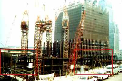
Above, is a photo of early construction work on the South Tower. Behind, is the North Tower and further back, the Verizon building. The photo was taken from the old extention of Greenwich Street (which was ripped up to make way for WTCs 4 and 5) looking north west. Some interesting aspects of the construction are presented in the following enlargements of the red-boxed regions.
In this enlargement one can see eight perimeter box columns at ten foot intervals (further up the structure these columns split into three smaller box columns at 40 inch intervals). Of course, what is of interest here are the eight (seven on the lower level and one on the upper) quite solid looking beams spanning the 35 foot gap between the perimeter wall and the central core, where the «official line» promised us there were only flimsy trusses.
In the foreground of this enlargement one can see eighteen perimeter box columns of the South Tower (those in the background are of the North Tower). If you look closely, you can just make out a single quite large beam spanning the 60 foot gap between the central core and the perimeter wall. Remember, that the corner core column to which this beam is attached is some 3 foot wide (and 16 inches deep). However, one floor below this, workers are working on a section of flooring held up by what appears to be trussing. One supposes that this is temporary flooring. If one looks carefully one can see a barrier rail to prevent workers from falling off the area supported by the trusses. This tends to support the case that this is temporary flooring.
Assuming that all the missing steel is contained in these beams we can estimate their cross-sectional area (the assumption that all the missing steel is contained in these beams is somewhat dubious, as I suspect that the sample of perimeter columns has been deliberately biased toward columns with thin cross-sections, and hence, that a significant percentage of the missing steel, is missing from the perimeter columns). Still, using this assumption, we have 1100 + 227 = 1327 cubic feet of steel to play with (the 227 comes from the no longer necessary double trussing). The total length of double trussing to be replaced is 4440 feet. Hence, the desired estimate of the cross-sectional area is:
1327/4440 x 144 = 43 square inches.
So, we have enough steel to replace the double trusses by H-beams (or I-beams, depending on how you view them) that are 24 inches deep, 10 inches wide and fabricated from one inch thick steel. These would be very, very strong beams, and would be much, much stronger than necessary to span the 35 and 60 foot spans from the central core to the perimeter wall.
It is worth emphasizing that these beams, plus the thicker stronger perimeter columns, would mean that WTC One and Two were actually traditional steel-framed buildings, that also incorporated extra thinner perimeter columns, to attain the rigidity necessary to resist wind loading.
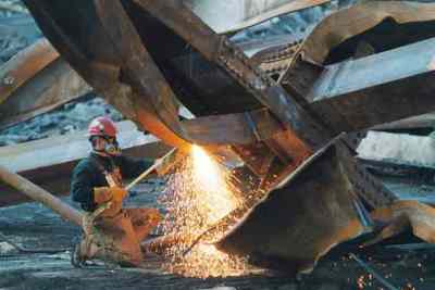
Above are pictures taken during the construction of the WTC. On the right is a picture of some 30 feet of trussing, which one supposes was temporary flooring. Note the vertical gaps in the box columns of the perimeter wall. Gaps in the box columns do not seem to be a sensible feature in a supposedly load bearing wall. Is this because the perimeter wall was not actually meant to be a load bearing wall as such, but a feature designed to give the WTC its required rigidity (against wind loading)? In the left photo note the yellow and red lines in the concrete. In the right photo note the three parallel light-colored lines (about 4 inches wide) in the concrete. One also wonders why the pile of steel in the foreground was hoisted up the building, unless it was to be incorporated in the structure. An answer to this question may be provided by the following photo.
Between the workers cutting up a couple of WTC core columns, is a column with concrete still attached to the beams that are welded/bolted to it. These U-shaped beams look suspiciously like the lengths of steel in the foreground of the picture of the trussing. Is it possible that floor slab was some eight inches thick and laced with significant steel beams? Was the slab poured in situ and not prefabricated as some claim? Was the temporary flooring only necessary till the concrete in the floor slabs had set? And where does the following piece fit in the whole affair?
Conclusion
• Impacts of the magnitude of those that occurred on September 11 were considered by the designers of the twin towers and the towers were designed to survive them.
• The possibility of a jet-fuel fires the size of those that occurred on September 11 were considered by the designers of the twin towers and the towers were designed to survive them.
• In order to explain why the towers collapsed, where other steel framed buildings would have survived, the WTC conspirators invented the «truss theory».
• The «truss theory» is seriously flawed. It cannot explain how the perimeter wall transmits wind loading to the central core.
• The «truss theory», if accepted, leads to a 33 percent underestimate of the amount of steel in the towers. That is, the «truss theory» does not account for the whereabouts of 32,000 tons of steel (of 96,000 tons) used in the construction of each of the towers.
• The «truss theory» is a lie that has been spun to convince a gullible public, that what appeared to be the controlled demolitions of three of the World Trade Center buildings, were actually natural consequents of the aircraft strikes and not controlled demolitions at all.
• There are photos showing large steel girders positioned where the «official» line states that only (double) trusses should be.
• In all, one has to conclude that the «truss theory» is false and that those who push it are part of a large conspiracy to deceive the American people.
Architects must provide World Trade Center blueprints and plans
Design architecture for the World Trade Center was provided by Minoru Yamasaki & Associates. Emery Roth & Sons served as the architect of record. Since these people have nothing to hide, they should provide the architectural plans of the World Trade Center, for all to see. This will enable any misunderstandings regarding the facts of the collapse to be established and corrected. In fact, Minoru Yamasaki & Associates, Roth & Sons, or their descendent companies, should put the entire set of architectural plans on the internet.
Официальный отчет
The WTC Report.
2.1 Building Descriptions
2.1.1 General

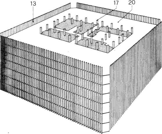
The WTC towers, also known as WTC 1 and WTC 2, were the primary components of the seven building World Trade Center complex. Each of the towers encompassed 110 stories above the Plaza level and seven levels below. WTC 1 (the north tower) had a roof height of 1,368 feet, briefly earning it the title of the world's tallest building. WTC 2 (the south tower) was nearly as tall, with a roof height of 1,362 feet. WTC 1 also supported a 360-foot-tall television and radio transmission tower. Each building had a square floor plate, 207 feet 2 inches long on each side. Corners were chamfered 6 feet 11 inches. Nearly an acre of floor space was provided at each level. A rectangular service core with overall dimensions of approximately 87 feet by 137 feet, was present at the center of each building, housing 3 exit stairways, 99 elevators, and 16 escalators. Note, that this description of the core is meant to mislead the reader by directing attention away from the cores main purpose, which was to support most, if not all, of the gravity load (weight) of the building and to reduce it to just «an entrance and exit». The core provided the strength needed to support the weight of the structure, while the outer wall provided the necessary rigidity to resist lateral loading due to the wind. Figure 2-1 presents a schematic plan of a representative above ground floor.
The project was developed by the Port Authority of New York and New Jersey (hereafter referred to as the Port Authority), a bi-state public agency. Original occupancy of the towers was dominated by government agencies, including substantial occupancy by the Port Authority itself. However, this occupancy evolved over the years and, by 2001, the predominant occupancy of the towers was by commercial tenants, including a number of prominent financial and insurance services firms.
Design architecture was provided by Minoru Yamasaki & Associates, and Emery Roth & Sons served as the architect of record. Since these companies have nothing to hide, they should provide the architectural plans of the WTC to the world, so that any misunderstandings regarding the facts of the collapse, may be established. In fact, Minoru Yamasaki & Associates, and Roth & Sons, or their descendent companies, should put the entire set of architectural plans on the internet. Skilling, Helle, Christiansen, Robertson were the project structural engineers; Jaros, Baum & Bolles were the mechanical engineers; and Joseph R. Loring & Associates were the electrical engineers. The Port Authority provided design services for site utilities, foundations, basement retaining walls, and paving. Ground breaking for construction was on August 5, 1966. Steel construction began in August 1968. First tenant occupancy of WTC 1 was in December 1970, and occupancy of WTC 2 began in January 1972. Ribbon cutting was on April 4, 1973.
2.1.2 Structural Description
WTC 1 and WTC 2 were similar, but not identical. WTC 1 was 6 feet taller than WTC 2 and also supported a 360-foot tall transmission tower. The service core in WTC 1 was oriented east to west, and the service core in WTC 2 was oriented north to south. Service core, service core,... more propaganda. The more you are told the core is just for servicing the building, the more you believe it. Right? In addition to these basic configuration differences, the presence of each building affected the wind loads on the other, resulting in a somewhat different distribution of design wind pressures, and, therefore, a somewhat different structural design of the lateral-force-resisting system. In addition, tenant improvements over the years resulted in removal of portions of floors and placement of new private stairways between floors, in a somewhat random pattern. Figure 2-2 presents a structural framing plan representative of an upper floor in the towers.
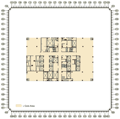 Figure 2-1 Representative floor plan (based on floor plan for 94th and 95th floors of WTC1).
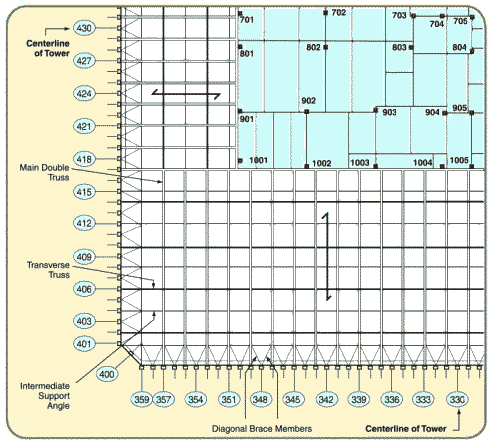 Figure 2-2 Representative structural framing plan, upper floors.
The buildings' signature architectural design feature was the vertical fenestration, the predominant element of which was a series of closely spaced built-up box columns. At typical floors, a total of 59 of these perimeter columns were present along each of the flat faces of the building. These columns were built up by welding four plates together to form an approximately 14-inch square section, spaced at 3 feet 4 inches on center. Adjacent perimeter columns were interconnected at each floor level by deep spandrel plates, typically 52 inches in depth. In alternate stories, an additional column was present at the center of each of the chamfered building corners. The resulting configuration of closely spaced columns and deep spandrels created a perforated steel bearing-wall frame system that extended continuously around the building perimeter.
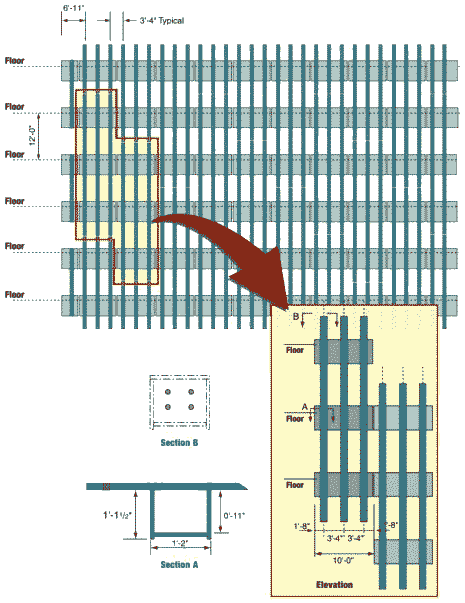 Figure 2-3 Partial elevation of exterior bearing-wall frame showing exterior wall module construction.
Figure 2-3 presents a partial elevation of this exterior wall at typical building floors. Construction of the perimeter-wall frame made extensive use of modular shop prefabrication. In general, each exterior wall module consisted of three columns, three stories tall, interconnected by the spandrel plates, using all-welded construction. Cap plates were provided at the tops and bottoms of each column, to permit bolted connection to the modules above and below. Access holes were provided at the inside face of the columns for attaching high-strength bolted connections. Connection strength varied throughout the building, ranging from four bolts at upper stories to six bolts at lower stories. Near the building base, supplemental welds were also utilized.
The buildings' signature architectural design feature was the vertical fenestration, the predominant element of which was a series of closely spaced built-up box columns. At typical floors, a total of 59 of these perimeter columns were present along each of the flat faces of the building. These columns were built up by welding four plates together to form an approximately 14-inch square section, spaced at 3 feet 4 inches on center. Adjacent perimeter columns were interconnected at each floor level by deep spandrel plates, typically 52 inches in depth. In alternate stories, an additional column was present at the center of each of the chamfered building corners. The resulting configuration of closely spaced columns and deep spandrels created a perforated steel bearing-wall frame system that extended continuously around the building perimeter.
Figure 2-3 presents a partial elevation of this exterior wall at typical building floors. Construction of the perimeter-wall frame made extensive use of modular shop prefabrication. In general, each exterior wall module consisted of three columns, three stories tall, interconnected by the spandrel plates, using all-welded construction. Cap plates were provided at the tops and bottoms of each column, to permit bolted connection to the modules above and below. Access holes were provided at the inside face of the columns for attaching high-strength bolted connections. Connection strength varied throughout the building, ranging from four bolts at upper stories to six bolts at lower stories. Near the building base, supplemental welds were also utilized.