Страница:
Side joints of adjacent modules consisted of high-strength bolted shear connections between the spandrels at mid-span. Except at the base of the structures and at mechanical floors (Figure 2-8 shows one of these mechanical floors. Note that all the perimeter wall columns are joined/spliced at this one level.) horizontal splices between modules were staggered in elevation so that not more than one third of the units were spliced in any one story. Where the units were all spliced at a common level, supplemental welds were used to improve the strength of these connections. Figure 2-3 illustrates the construction of typical modules and their interconnection. At the building base, adjacent sets of three columns tapered to form a single massive column, in a fork-like formation, shown in Figure 2-4.
 Figure 2-4 Base of exterior wall frame.
Twelve grades of steel, having yield strengths varying between 42 kips per square inch (ksi) and 100 ksi, were used to fabricate the perimeter column and spandrel plates as dictated by the computed gravity and wind demands. Plate thickness also varied, both vertically and around the building perimeter, to accommodate the predicted loads and minimize differential shortening of columns across the floor plate. In upper stories of the building, plate thickness in the exterior wall was generally 1/4 inch. At the base of the building, column plates as thick as 4 inches were used. Arrangement of member types (grade and thickness) was neither exactly symmetrical within a given building nor the same in the two towers. One would definitely be interested in the arrangement of member types, especially whether or not the perimeter wall had columns with say, 2 inch thickness, regularly interspersed among those of 1/4 inch thickness. These would then form the frame of a regular steel-framed building.
The stiffness of the spandrel plates, created by the combined effects of the short spans (Not true. To obtain the required stiffness, the spandrel plates were bolted together to form a very long span. In fact, they spanned right around the building.) and significant depth (True.) created a structural system that was stiff both laterally and vertically. Under the effects of lateral wind loading, the buildings essentially behaved as cantilevered hollow structural tubes with perforated walls. Just think of the perimeter wall as a massive box column, with hundreds of small holes cut in it. In each building, the windward wall acted as a tension flange for the tube while the leeward wall acted as a compression flange. The side walls acted as the webs of the tube, and transferred shear between the windward and leeward walls through Vierendeel action (Figure 2-5).
 Figure 2-5 Structural tube frame behavior.
Vierendeel action occurs in rigid trusses that do not have diagonals. In such structures, stiffness is achieved through the flexural (bending) strength of the connected members. In the lower seven stories of the towers, where there were fewer columns (Figure 2-4), vertical diagonal braces were in place at the building cores to provide this stiffness. This structural frame was considered to constitute a tubular system.
Floor construction typically consisted of 4 inches of lightweight concrete on 1-1/2-inch, 22-gauge non-composite steel deck. In the core area, slab thickness was 5 inches. Remember, that it is important for the «official line» that there be a discontinuity between «inside the core» and «outside the core». Hence, the 5 inch slab inside the core and 4 inch slab outside the core. Outside the central core, the floor deck was supported by a series of composite floor trusses that spanned between the central core and exterior wall. I claim that this is nonsense, see the article The World Trade Center Demolition. Composite behavior with the floor slab was achieved by extending the truss diagonals above the top chord so that they would act much like shear studs, as shown in Figure 2-6.
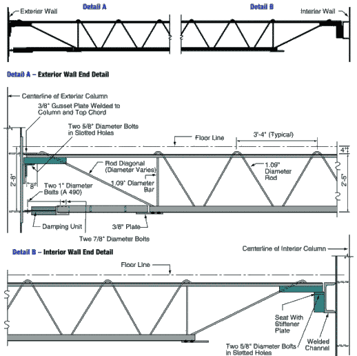 Figure 2-6 Floor truss member with detail of end connections.
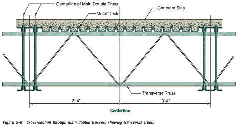
Detailing of these trusses was similar to that employed in open-web joist fabrication and, in fact, the trusses were manufactured by a joist fabricator, the LaClede Steel Corporation. However, the floor system design was not typical of open-web-joist floor systems. It was considerably more redundant and was well braced with transverse members. Trusses were placed in pairs, with a spacing of 6 feet 8 inches and spans of approximately 60 feet to the sides and 35 feet at the ends of the central core. Why would anyone place pairs of trusses at 6 feet 8 inch intervals, when the trusses could be placed regularly at 3 feet 4 inch intervals, at no extra cost and greatly increased stability? Metal deck spanned parallel to the main trusses and was directly supported by continuous transverse bridging trusses spaced at 13 feet 4 inches and intermediate deck support angles spaced at 6 feet 8 inches from the transverse trusses. The combination of main trusses, transverse trusses, and deck support enabled the floor system to act as a grillage to distribute load to the various columns.
At the exterior wall, truss top chords were supported in bearing off seats extending from the spandrels at alternate columns. Welded plate connections with an estimated ultimate capacity of 90 kips (refer to Appendix B) tied the pairs of trusses to the exterior wall for out-of-plane forces. At the central core, trusses were supported on seats off a girder that ran continuously past and was supported by the core columns. Nominal out-of-plane connection was provided between the trusses and these girders.
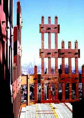
Figure 2-7 Shows the erection of prefabricated components, forming exterior wall and floor deck units.
This is a view from the North Tower, looking north toward the Empire State Building. Note the yellow and red lines in the concrete. What are these? Note, in particular, the three V-shaped features in/on the concrete, along the north wall (but not along the west wall).
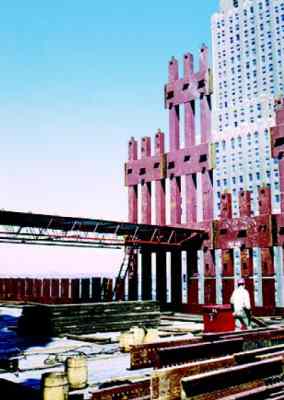 Figure 2-8 Shows the erection of floor framing during original construction.
This is another view from the North Tower (looking north west). The other high-rise is the Verizon building. Note the vertical gaps in the box columns of the perimeter wall. Gaps in the box columns do not seem to be a sensible feature in a supposedly load bearing wall. Is this because the perimeter wall was not required to carry much of the weight of the building, but was mainly a feature designed to give the WTC its required rigidity (against wind loading)? Notice the three parallel light-colored lines (about 4 inches wide) in the concrete. One also wonders why the pile of steel in the foreground was hoisted up the building, unless it was to be incorporated in the structure.
These figures illustrate this construction, and Figure 2-9 shows a cross-section through typical floor framing. Floors were designed for a uniform live load of 100 pounds per square foot (psf) over any 200-square-foor area with allowable live load reductions taken over larger areas. At building corners, this amounted to a uniform live load (unreduced) of 55 psf.
 At approximately 10,000 locations in each building, viscoelastic dampers extended between the lower chords of the joists and gusset plates mounted on the exterior columns beneath the stiffened seats (Detail A in Figure 2-6). I find it really strange that dampers are attached to only one end of each truss. It doesn't make much sense to dampen vibration at one end while letting the other end «blow in the breeze». These dampers were the first application of this technology in a high-rise building, and were provided to reduce occupant perception of wind-induced building motion.
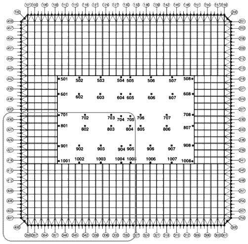 Figure 2-2 Representative structural framing plan, upper floors.
You may wish to compare the above floor plan with this one taken from Godfrey, GB (Editor); Multi-Storey Buildings in Steel, Second Edition; Collins, London, England,1985, ISBN 0 00 383031 4. The differences are quite telling.
 Figure 2-2-A Structural system for typical floor.
The numbers in the figure denote:
13 — Perimeter frame
14 — Bar joists 900 mm deep
15 — Secondary joists
16 — Horizontal floor bracing
17 — Core box columns
That the second floor plan is more accurate than the first, is plain from the above photo where the diagonal brace members (the V-shaped features in the diagrams) are clearly visible in the concrete along the north wall, but not along the west wall (as in the second diagram but not the first).
Pairs of flat bars extended diagonally from the exterior wall to the top chord of adjacent trusses (this is puzzling, as the top chords of the trusses are set in the concrete slab, yet one can clearly see these bars on the concrete surface in the above mentioned photo). These diagonal flat bars, which were typically provided with shear studs, provided horizontal shear transfer between the floor slab and exterior wall, as well as out-of-plane bracing for perimeter columns not directly supporting floor trusses (Figure 2-2).
The core consisted of 5-inch concrete fill on metal deck supported by floor framing of rolled structural shapes, in turn supported by a combination of wide flange shape and box-section columns. Some of these columns were very large, with cross-sections measuring 14 inches wide by 36 inches deep. In upper stories, these rectangular box columns transitioned into heavy rolled wide flange shapes (see Appendix B for a picture of the transition from box column to H-column).
Between the 106th and 110th floors, a series of diagonal braces were placed into the building frame. These diagonal braces together with the building columns and floor framing formed a deep outrigger truss system that extended between the exterior walls and across the building core framing. A total of 10 outrigger truss lines were present in each building
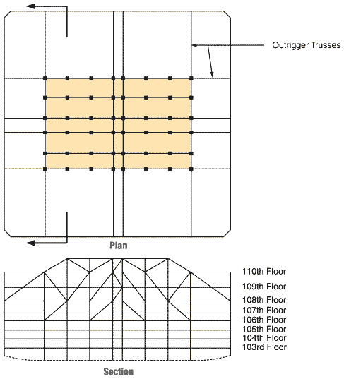 Figure 2-10 Outriger truss system at tower roof.
(Figure 2-10), 6 extending across the long direction of the core and 4 extending across the short direction of the core. This outrigger truss system provided stiffening of the frame for wind resistance, mobilized some of the dead weight supported by the core to provide stability against wind-induced overturning, and also provided direct support for the transmission tower on WTC 1. Although WTC 2 did not have a transmission tower, the outrigger trusses in that building were also designed to support such a tower.
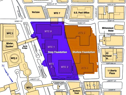 Figure 2-11. Location of subterranean structure.
A deep subterranean structure was present beneath the WTC Plaza (Figure 2-11) and the two towers. The western half of this substructure, bounded by West Street to the west and by the 1/9 subway line that extends approximately between West Broadway and Greenwich Street on the east, was 70 feet deep and contained six subterranean levels. The structure housed a shopping mall and building mechanical and electrical services, and it also provided a station for the PATH subway line and parking for the complex.
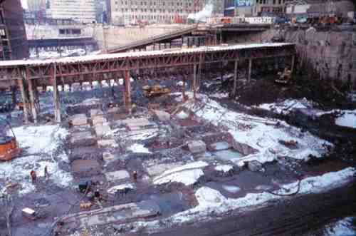
Above, is a photo of the area shaded in blue, in Figure 2-11 (looking north). In the foreground, are the foundations for the central core of the South Tower. The North Tower can be seen on the left further back. Two subway lines can be seen crossing the site (the two bridge-like structures). The site extended from West Street in the west to the old extention of Greenwich Street in the east (which was ripped up to make way for WTCs 4 and 5) and from Vesey Street in the north to Liberty Street in the south.
Prior to construction, the site was underlain by deep deposits of fill material, informally placed over a period of several hundred years to displace the adjacent Hudson River shoreline and create additional usable land area. In order to construct this structure, the eventual perimeter walls for the subterranean structure were constructed using the slurry wall technique. After the concrete wall was cured and attained sufficient strength, excavation of the basement was initiated. As excavation proceeded downward, tieback anchors were drilled diagonally down through the wall and grouted into position in the rock deep behind the walls. These anchors stabilized the wall against the soil and water pressures from the unexcavated side as the excavation continued on the inside. After the excavation was extended to the desired grade, foundations were formed and poured against the exposed bedrock, and the various subgrade levels of the structure were constructed.
Floors within the substructure were of reinforced concrete flat-slab construction, supported by structural steel columns. Many of these steel columns also provided support for the structures located above the plaza level. After the floor slabs were constructed, they were used to provide lateral support for the perimeter walls, holding back the earth pressure from the unexcavated side. The tiebacks, which had been installed as a temporary stabilizing measure, were decommissioned by cutting off their end anchorage hardware and repairing the pockets in the slurry wall where these anchors had existed.
Tower foundations beneath the substructure consisted of massive spread footings, socketed into and bearing directly on the massive bedrock. Steel grillages, consisting of layers of orthogonally placed steel beams, were used to transfer the immense column loads, in bearing, to the reinforced concrete footings.
2.1.3 Fire Protection
2.1.3.1 Passive Protection
2.1.3.2 Suppression
2.1.3.3 Smoke Management
2.1.3.4 Fire Department Features
2.1.4 Emergency Egress
2.1.5 Emergency Power
2.1.6 Management Procedures
2.2 Building Response
2.2.1 WTC 1
2.2.1.1 Initial Damage From Aircraft Impact
2.2.1.2 Fire Development
Twelve grades of steel, having yield strengths varying between 42 kips per square inch (ksi) and 100 ksi, were used to fabricate the perimeter column and spandrel plates as dictated by the computed gravity and wind demands. Plate thickness also varied, both vertically and around the building perimeter, to accommodate the predicted loads and minimize differential shortening of columns across the floor plate. In upper stories of the building, plate thickness in the exterior wall was generally 1/4 inch. At the base of the building, column plates as thick as 4 inches were used. Arrangement of member types (grade and thickness) was neither exactly symmetrical within a given building nor the same in the two towers. One would definitely be interested in the arrangement of member types, especially whether or not the perimeter wall had columns with say, 2 inch thickness, regularly interspersed among those of 1/4 inch thickness. These would then form the frame of a regular steel-framed building.
The stiffness of the spandrel plates, created by the combined effects of the short spans (Not true. To obtain the required stiffness, the spandrel plates were bolted together to form a very long span. In fact, they spanned right around the building.) and significant depth (True.) created a structural system that was stiff both laterally and vertically. Under the effects of lateral wind loading, the buildings essentially behaved as cantilevered hollow structural tubes with perforated walls. Just think of the perimeter wall as a massive box column, with hundreds of small holes cut in it. In each building, the windward wall acted as a tension flange for the tube while the leeward wall acted as a compression flange. The side walls acted as the webs of the tube, and transferred shear between the windward and leeward walls through Vierendeel action (Figure 2-5).
Vierendeel action occurs in rigid trusses that do not have diagonals. In such structures, stiffness is achieved through the flexural (bending) strength of the connected members. In the lower seven stories of the towers, where there were fewer columns (Figure 2-4), vertical diagonal braces were in place at the building cores to provide this stiffness. This structural frame was considered to constitute a tubular system.
Floor construction typically consisted of 4 inches of lightweight concrete on 1-1/2-inch, 22-gauge non-composite steel deck. In the core area, slab thickness was 5 inches. Remember, that it is important for the «official line» that there be a discontinuity between «inside the core» and «outside the core». Hence, the 5 inch slab inside the core and 4 inch slab outside the core. Outside the central core, the floor deck was supported by a series of composite floor trusses that spanned between the central core and exterior wall. I claim that this is nonsense, see the article The World Trade Center Demolition. Composite behavior with the floor slab was achieved by extending the truss diagonals above the top chord so that they would act much like shear studs, as shown in Figure 2-6.
Detailing of these trusses was similar to that employed in open-web joist fabrication and, in fact, the trusses were manufactured by a joist fabricator, the LaClede Steel Corporation. However, the floor system design was not typical of open-web-joist floor systems. It was considerably more redundant and was well braced with transverse members. Trusses were placed in pairs, with a spacing of 6 feet 8 inches and spans of approximately 60 feet to the sides and 35 feet at the ends of the central core. Why would anyone place pairs of trusses at 6 feet 8 inch intervals, when the trusses could be placed regularly at 3 feet 4 inch intervals, at no extra cost and greatly increased stability? Metal deck spanned parallel to the main trusses and was directly supported by continuous transverse bridging trusses spaced at 13 feet 4 inches and intermediate deck support angles spaced at 6 feet 8 inches from the transverse trusses. The combination of main trusses, transverse trusses, and deck support enabled the floor system to act as a grillage to distribute load to the various columns.
At the exterior wall, truss top chords were supported in bearing off seats extending from the spandrels at alternate columns. Welded plate connections with an estimated ultimate capacity of 90 kips (refer to Appendix B) tied the pairs of trusses to the exterior wall for out-of-plane forces. At the central core, trusses were supported on seats off a girder that ran continuously past and was supported by the core columns. Nominal out-of-plane connection was provided between the trusses and these girders.
Figure 2-7 Shows the erection of prefabricated components, forming exterior wall and floor deck units.
This is a view from the North Tower, looking north toward the Empire State Building. Note the yellow and red lines in the concrete. What are these? Note, in particular, the three V-shaped features in/on the concrete, along the north wall (but not along the west wall).
This is another view from the North Tower (looking north west). The other high-rise is the Verizon building. Note the vertical gaps in the box columns of the perimeter wall. Gaps in the box columns do not seem to be a sensible feature in a supposedly load bearing wall. Is this because the perimeter wall was not required to carry much of the weight of the building, but was mainly a feature designed to give the WTC its required rigidity (against wind loading)? Notice the three parallel light-colored lines (about 4 inches wide) in the concrete. One also wonders why the pile of steel in the foreground was hoisted up the building, unless it was to be incorporated in the structure.
These figures illustrate this construction, and Figure 2-9 shows a cross-section through typical floor framing. Floors were designed for a uniform live load of 100 pounds per square foot (psf) over any 200-square-foor area with allowable live load reductions taken over larger areas. At building corners, this amounted to a uniform live load (unreduced) of 55 psf.
You may wish to compare the above floor plan with this one taken from Godfrey, GB (Editor); Multi-Storey Buildings in Steel, Second Edition; Collins, London, England,1985, ISBN 0 00 383031 4. The differences are quite telling.
The numbers in the figure denote:
13 — Perimeter frame
14 — Bar joists 900 mm deep
15 — Secondary joists
16 — Horizontal floor bracing
17 — Core box columns
That the second floor plan is more accurate than the first, is plain from the above photo where the diagonal brace members (the V-shaped features in the diagrams) are clearly visible in the concrete along the north wall, but not along the west wall (as in the second diagram but not the first).
Pairs of flat bars extended diagonally from the exterior wall to the top chord of adjacent trusses (this is puzzling, as the top chords of the trusses are set in the concrete slab, yet one can clearly see these bars on the concrete surface in the above mentioned photo). These diagonal flat bars, which were typically provided with shear studs, provided horizontal shear transfer between the floor slab and exterior wall, as well as out-of-plane bracing for perimeter columns not directly supporting floor trusses (Figure 2-2).
The core consisted of 5-inch concrete fill on metal deck supported by floor framing of rolled structural shapes, in turn supported by a combination of wide flange shape and box-section columns. Some of these columns were very large, with cross-sections measuring 14 inches wide by 36 inches deep. In upper stories, these rectangular box columns transitioned into heavy rolled wide flange shapes (see Appendix B for a picture of the transition from box column to H-column).
Between the 106th and 110th floors, a series of diagonal braces were placed into the building frame. These diagonal braces together with the building columns and floor framing formed a deep outrigger truss system that extended between the exterior walls and across the building core framing. A total of 10 outrigger truss lines were present in each building
(Figure 2-10), 6 extending across the long direction of the core and 4 extending across the short direction of the core. This outrigger truss system provided stiffening of the frame for wind resistance, mobilized some of the dead weight supported by the core to provide stability against wind-induced overturning, and also provided direct support for the transmission tower on WTC 1. Although WTC 2 did not have a transmission tower, the outrigger trusses in that building were also designed to support such a tower.
A deep subterranean structure was present beneath the WTC Plaza (Figure 2-11) and the two towers. The western half of this substructure, bounded by West Street to the west and by the 1/9 subway line that extends approximately between West Broadway and Greenwich Street on the east, was 70 feet deep and contained six subterranean levels. The structure housed a shopping mall and building mechanical and electrical services, and it also provided a station for the PATH subway line and parking for the complex.
Above, is a photo of the area shaded in blue, in Figure 2-11 (looking north). In the foreground, are the foundations for the central core of the South Tower. The North Tower can be seen on the left further back. Two subway lines can be seen crossing the site (the two bridge-like structures). The site extended from West Street in the west to the old extention of Greenwich Street in the east (which was ripped up to make way for WTCs 4 and 5) and from Vesey Street in the north to Liberty Street in the south.
Prior to construction, the site was underlain by deep deposits of fill material, informally placed over a period of several hundred years to displace the adjacent Hudson River shoreline and create additional usable land area. In order to construct this structure, the eventual perimeter walls for the subterranean structure were constructed using the slurry wall technique. After the concrete wall was cured and attained sufficient strength, excavation of the basement was initiated. As excavation proceeded downward, tieback anchors were drilled diagonally down through the wall and grouted into position in the rock deep behind the walls. These anchors stabilized the wall against the soil and water pressures from the unexcavated side as the excavation continued on the inside. After the excavation was extended to the desired grade, foundations were formed and poured against the exposed bedrock, and the various subgrade levels of the structure were constructed.
Floors within the substructure were of reinforced concrete flat-slab construction, supported by structural steel columns. Many of these steel columns also provided support for the structures located above the plaza level. After the floor slabs were constructed, they were used to provide lateral support for the perimeter walls, holding back the earth pressure from the unexcavated side. The tiebacks, which had been installed as a temporary stabilizing measure, were decommissioned by cutting off their end anchorage hardware and repairing the pockets in the slurry wall where these anchors had existed.
Tower foundations beneath the substructure consisted of massive spread footings, socketed into and bearing directly on the massive bedrock. Steel grillages, consisting of layers of orthogonally placed steel beams, were used to transfer the immense column loads, in bearing, to the reinforced concrete footings.
2.1.3 Fire Protection
The fire safety of a building is provided by a system of interdependent fire protection features, including suppression systems, detection systems, notification devices, smoke management systems, and passive systems such as compartmentation and structural protection. The failure of any of these fire protection systems will impact the effectiveness of the other systems in the building.
2.1.3.1 Passive Protection
In WTC 1, structural elements up to the 39th floor were originally protected from fire with a spray applied product containing asbestos (Nicholson, et al. 1980). These asbestos-containing materials were later abated inside the building, either through encapsulation or replacement. On all other floors and throughout WTC 2, a spray-applied, asbestos-free mineral fiber material was used. Each element of the steel floor trusses was protected with spray-applied material. The specific material used was a low-density, factory-mixed product consisting of manufactured inorganic fibers, proprietary cement-type binders, and other additives in low concentrations to promote wetting, set, and dust control. Air setting, hydraulic setting, and ceramic setting binders were added in varying quantities and combinations or singly at the site, depending on the particular application and weather conditions. Finally, water was added at the nozzle of the spray gun as the material was sprayed onto the member to be protected. The average thickness of spray-applied fire proofing on the trusses was 3/4 inch. In the mid-1990s, a decision was made to upgrade the fire protection by applying additional material onto the trusses so as to increase fire proofing thickness to 1-1/2 inches (somehow, I doubt that 3 inches (1-1/2 inches «either side») of fire proofing would stick to the 1.09 inch diagonal rod of the trusses). The fire proofing upgrade was applied to individual floors as they became vacant. By September 11, 2001, a total of 31 stories had been upgraded, including the entire impact zone in WTC 1 (floors 94-98), but only the 78th floor in the impact zone in WTC 2 (floors 78-84).
Spandrels and girders were specified to have sufficient protection to achieve a 3-hour rating. Except for the interior face of perimeter columns between spandrels, which were protected with a plaster material, spray applied materials similar to those used on the floor systems were used. The thickness of protection on spandrels and girders varied, with the more massive steel column sections receiving reduced fire proofing thickness relative to the thinner elements.
The primary vertical compartmentation was provided by the floor slabs that were cast flush against the spandrel beams at the exterior wall, providing separation between floors at the building perimeter. After a fire in 1975 (note that this fire did not cause the building to collapse) vertical penetrations for cabling and plumbing were sealed with fire-resistant material. At stair and elevator shafts, separation was provided by a wall system constructed of metal studs and two layers of 5/8— inch thick gypsum board on the exterior and one layer of 5/8-inch thick gypsum board on the interior. These assemblies provided a 2-hour rating. Horizontal compartmentation varied throughout the complex. Some separating walls ran from slab to slab, while others extended only up to the suspended ceiling. A report by the New York Board of Fire Underwriters (NYBFU) titled One World Trade Center Fire, February 13, 1975 (NYBFU 1975) presents a detailed discussion of the compartmentation features of the building at that time.
2.1.3.2 Suppression
When originally constructed, the two towers were not provided with automatic fire sprinkler protection. However, such protection was installed as a retrofit circa 1990, and automatic sprinklers covered nearly 100 percent of WTC 1 and WTC 2 at the time of the September 11 attacks. In addition, each building had standpipes running through each of its three stairways. A 1.5-inch hose line and a cabinet containing two air pressurized water (APW) extinguishers were also present at each floor in each stairway.
The primary water supply was provided by a dedicated fire yard main that looped around most of the complex. This yard main was supplied directly from the municipal water supply. Two remotely located high pressure, multi-stage, 750-gallons per minute (gpm) electrical fire pumps took suction from the New York City municipal water supply and produced the required operating pressures for the yard main.
Each tower had three electrical fire pumps that provided additional pressure for the standpipes. One pump, located on the 7th floor, received the discharge from the yard main fire pumps and moved it up to the 41st floor, where a second 750-gpm fire pump pushed it up to a third pump on the 75th floor. Each fire pump produced sufficient pressure to supply water to the pump two stages up from it in the event that any one pump should fail. Several 5,000-gallon storage tanks, filled from the domestic water system, provided a secondary water supply. Tanks on the 41st, 75th, and 110th floors provided water directly to a standpipe system. A tank on the 20th floor supplied water directly to the yard main. Numerous Fire Department of New York (FDNY) connections were located around the complex to allow the fire department to boost water pressure in the buildings.
2.1.3.3 Smoke Management
A zoned smoke control system was built into each building's ventilation systems and was activated upon direction of the responding FDNY Incident Commander. The system was designed to limit smoke spread from the tenant areas to the core area, thereby assisting both individuals evacuating from an area and those responding to the scene by limiting smoke spread into the core.
2.1.3.4 Fire Department Features
At the time of the 1993 World Trade Center bombing, a centralized Fire Command Center (FCC) for the two towers was present at the Concourse level. This FCC was located in the B-1 level Operations Control Center (OCC). Following the 1993 bombing, additional FCCs were installed in the lobbies of each tower.
A Radiax cable and antenna were installed in the WTC complex to facilitate the use of FDNY radios in the towers. Fire department telephones were provided in both towers on odd floors in Stairway 3, as well as on levels B-1, B-4, and B-6.
The WTC had its own fire brigade, consisting of Port Authority police officers trained in fire safety, who worked with the FDNY to investigate fire conditions and take appropriate actions. The internal fire brigade had access to fire carts located on the Concourse level and on the 44th and 78th floor sky lobbies of each tower. These fire carts were equipped with hoses, nozzles, self-contained breathing apparatus, turnout coats, forcible entry tools, resuscitators, first-aid kits, and other emergency equipment. Typically, the WTC fire brigade would collect the nearest fire cart and set up operations on the floor below the fire floor.
The WTC complex had 24 Siamese connections located at street level for use by the FDNY apparatus. Each of these Siamese connections served various portions of the complex and was identified as such.
2.1.4 Emergency Egress
Each tower was provided with three independent emergency fire exit stairways, located in the core of the building, as indicated in Figure 2-12. Two of these stairways, designated Stairway 1 and Stairway 2, were 44 inches wide and ran to the 110th floor. The third stairway, designated Stairway 3, had a width of 56 inches and ran to the 108th floor. The stairways did not run in continuous vertical shafts from the top to the bottom of the structure. Instead, the plan location of the stairways shifted at some levels, and occupants traversing the stairways were required to move from one vertical shaft to another through a transfer corridor. Both Stairways 1 and 2 had transfers at the 42nd, 48th, 76th, and 82nd levels. Stairway 1 had an additional transfer at the 26th level and Stairway 3 had a single transfer at the 76th level. After the 1993 bombing, battery-operated emergency lighting was provided in the stairways and photoluminescent paint was placed on the edge of the stair treads to facilitate emergency egress.
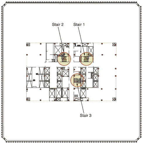 Figure 2-12. Floor plan of 94th and 95th floors of WTC 1 showing egress stairways.
There were 99 elevators in each of the two towers, including 23 express elevators; however, the express elevators were not intended to be used for emergency access or egress. There were also several freight elevators servicing groups of floors in the buildings. The several elevators that served each floor were broken into two groups that operated on different power supplies.
Upon alarm activation, an automatic elevator override system commanded all elevators serving or affected by a fire area to immediately return to the ground floor, or to their sky lobby (44th and 78th floors). From there, the elevators could be operated manually by the FDNY. Although many fire departments routinely use elevators to provide better access in high-rise buildings, FDNY does not do this, because there have been fatalities associated with such use.
2.1.5 Emergency Power
Primary power was provided at 13.8 kilovolts (kV) through a ground level substation in WTC 7 near the Barclay Street entrance to the underground parking garage. The primary power was wired to the buildings through two separate systems. The first provided power throughout each building; the second provided power to emergency systems in the event that the primary wiring system failed.
Six 1,200-kilowatt (kW) emergency power generators located in the sixth basement (B-6) level provided a secondary power supply. These generators were checked on a routine basis to ensure that they would function properly during an emergency. This equipment provided backup power for communications equipment, elevators, emergency lighting in corridors and stairwells, and fire pumps. Telephone systems were provided with an independent battery backup system. Emergency lighting units in exit stairways, elevator lobbies, and elevator cabs were equipped with individual backup batteries.
Six 1,200-kilowatt (kW) emergency power generators located in the sixth basement (B-6) level provided a secondary power supply. These generators were checked on a routine basis to ensure that they would function properly during an emergency. This equipment provided backup power for communications equipment, elevators, emergency lighting in corridors and stairwells, and fire pumps. Telephone systems were provided with an independent battery backup system. Emergency lighting units in exit stairways, elevator lobbies, and elevator cabs were equipped with individual backup batteries.
2.1.6 Management Procedures
The Port Authority has a risk management group that coordinates fire and safety activities for their various properties. This group provided training for the WTC fire brigade, fire safety directors, and tenant fire wardens. The WTC had 25 fire safety directors who assisted in the coordination of fire safety activities in the buildings throughout the year. Six satellite communication stations, staffed by deputy fire safety directors, were spaced throughout the towers. In addition, each tenant was required to provide at least one fire warden. Tenants that occupied large areas of the building were required to provide one fire warden for every 7,500 square feet of occupied space. The fire safety directors trained the fire wardens and fire drills were held twice a year.
2.2 Building Response
WTC 1 and WTC 2 each experienced a similar, though not identical, series of loading events. In essence, each tower was subjected to three separate, but related events (actually, there were four separate, but related events, the last being the detonation of a multitude of small explosive charges in each building). The sequence of these events was the same for the two buildings, although the timing was not. In each case, the first loading event was a Boeing 767-200ER series commercial aircraft hitting the building, together with a fireball (Although dramatic, these fireballs did not explode or generate a shock wave. If an explosion or detonation had occurred, the expansion of the burning gasses would have taken place in microseconds, not the 2 seconds observed. Therefore, although there were some overpressures, it is unlikely that the fireballs, being external to the buildings, would have resulted in significant structural damage.) resulting from immediate rapid ignition of a portion of the fuel on board the aircraft. Boeing 767-200ER aircraft have a maximum rated takeoff weight of 395,000 pounds, a wingspan of 156 feet 1 inch, and a rated cruise speed of 530 miles per hour. The aircraft is capable of carrying up to 23,980 gallons of fuel and it is estimated that, at the time of impact, each aircraft had approximately 10,000 gallons of unused fuel on board (compiled from Government sources). Boeing 707-320B aircraft have a maximum rated takeoff weight of 336,000 pounds, a wingspan of 145 feet 9 inches, and a rated cruise speed of 607 miles per hour. The aircraft is capable of carrying over 23,000 gallons of fuel. The Boeing 707 and 767 are very similar aircraft. Under normal flying conditions, a Boeing 707 would smash into a building with about 10 percent more energy than would the slightly heavier Boeing 767. Engineers designed the World Trade Center towers to withstand a collision with a Boeing 707. Hence, they were necessarily designed to survive the impact of a Boeing 767. See The World Trade Center Demolition and Microsoft Software Used To Simulate The Crash Of A Boeing 747 Into The World Trade Centre.
In each case, the aircraft impacts resulted in severe structural damage, including some localized partial collapse, but did not result in the initiation of global collapse. In fact, WTC 1 remained standing for a period of approximately 1 hour and 43 minutes, following the initial impact; WTC 2 remained standing for approximately 56 minutes following impact. The second event was the simultaneous ignition and growth of fires over large floor areas on several levels of the buildings. The fires heated the structural systems and, over a period of time, resulted in additional stressing of the damaged structure, as well as sufficient additional damage and strength loss to initiate the third event, a progressive sequence of failures that culminated in total collapse of both structures. Of course, this does not even begin to explain the total collapse of WTC Seven.
In each case, the aircraft impacts resulted in severe structural damage, including some localized partial collapse, but did not result in the initiation of global collapse. In fact, WTC 1 remained standing for a period of approximately 1 hour and 43 minutes, following the initial impact; WTC 2 remained standing for approximately 56 minutes following impact. The second event was the simultaneous ignition and growth of fires over large floor areas on several levels of the buildings. The fires heated the structural systems and, over a period of time, resulted in additional stressing of the damaged structure, as well as sufficient additional damage and strength loss to initiate the third event, a progressive sequence of failures that culminated in total collapse of both structures. Of course, this does not even begin to explain the total collapse of WTC Seven.
2.2.1 WTC 1
2.2.1.1 Initial Damage From Aircraft Impact
American Airlines Flight 11 struck the north face of WTC 1 approximately between the 94th and 98th floors (Figures 2-13 and 2-14), causing massive damage to the north face of the building within the immediate area (Figure 2-15).
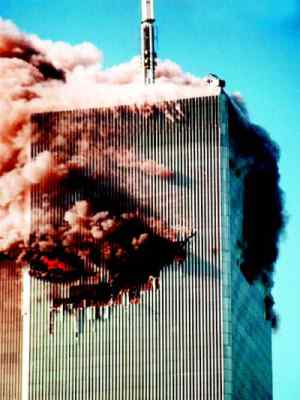 Figure 2-13 Zone of aircraft impact on the north face of WTC 1.
At the central zone of impact corresponding to the airplane fuselage and engines, at least five of the prefabricated, three-column sections that formed the exterior walls were broken loose of the structure, and some were pushed inside the building envelope.
 Figure 2-15 Impact damage to the north face of WTC 1.
Locally, floors supported by these exterior wall sections appear to have partially collapsed, losing their support along the exterior wall. Away from this central zone, in areas impacted by the outer wing structures, the exterior columns were fractured by the force of the collision. Interpretation of photographic evidence suggests that from 31 to 36 columns on the north building face were destroyed over portions of a four-story range. Partial collapse of floors in this zone appear to have occurred over a horizontal length of wall of approximately 65 feet, while floors in other portions of the building appear to have remained intact. Figure 2-16 shows the damage to the exterior columns on the impacted face of WTC 1.
 General notes:
(1) column damage captured from photographs and enchanced video,
(2) Damage to column lines 111-115 at level 96 is estimated.
Figure 2-16 Impact damage to exterior columns on the north face of WTC 1.
In addition to this damage at the building perimeter, a significant but undefined amount of damage also occurred to framing at the central core. For an estimate of the likely damage to the central core (by the University of California, Berkeley professor, Astaneh-Asl) see the article Microsoft Software Used To Simulate The Crash Of A Boeing 747 Into The World Trade Centre. This article claims that the damage caused by the much, much larger and heavier Boeing 747, in a collision with the World Trade Center, would be insufficient to bring the central core down. Interviews were conducted with persons who were present in offices on the 91st floor of the building at the north face of the structure, three floors below the approximate zone of impact. Their descriptions of the damage evident at this floor level immediately following the aircraft impact suggest relatively slight damage at the exterior wall of the building, but progressively greater damage to the south and east. They described extensive building debris in the eastern portion of the central core, preventing their access to the easternmost exit stairway. This suggests the possibility of immediate partial collapse of framing in the central core. These persons also described the presence of debris from collapsed partition walls from upper floors in stairways located further to the west, suggesting the possibility of some structural damage in the northwestern portion of the core framing as well. Figure 2-17 is a sketch made during an interview with building occupants indicating portions of the 91st floor that could not be accessed due to accumulated debris.
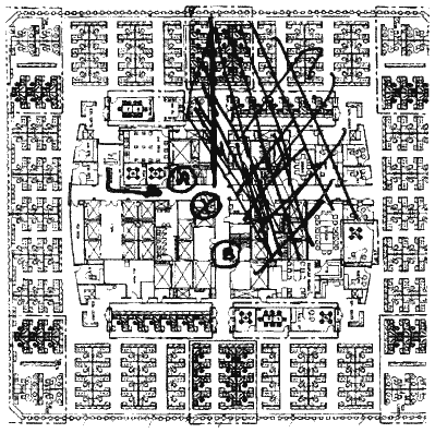 Figure 2-17 Approximate debris location on the 91st floor of WTC 1.
It is known that some debris from the aircraft traveled completely through the structure. For example, life jackets and portions of seats from the aircraft were found on the roof of the Bankers Trust building, located to the south of WTC 2. Part of the landing gear from this aircraft was found at the corner of West and Rector Streets, some five blocks south of the WTC complex (Figure 2-18).
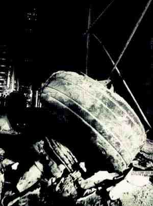 Figure 2-18 Landing gear found at the corner of West and Rector Streets.
As this debris passed through the building, it doubtless caused some level of damage to the structure across the floor plate, including, potentially, interior framing, core columns, framing at the east, south, and west walls, and the floors themselves. The exact extent of this damage will likely never be known with certainty. It is evident that, despite this damage, the structure retained sufficient integrity and strength to remain globally stable for a period of approximately 1 hour and 43 minutes.
The building's structural system, composed of the exterior loadbearing frame, the gravity loadbearing frame at the central core, and the system of deep outrigger trusses in upper stories, was highly redundant. This permitted the building to limit the immediate zone of collapse to the area where several stories of exterior columns were destroyed by the initial impact and, perhaps, to portions of the central core as previously described. Following the impact, floor loads originally supported by the exterior columns in compression were successfully transferred to other load paths. Most of the load supported by the failed columns is believed to have transferred to adjacent perimeter columns through Vierendeel behavior of the exterior wall frame. This is not true. The extra vertical load on the perimeter columns would have distributed itself symmetrically around the perimeter frame (and would not have been concentrated on the adjacent columns). Preliminary structural analyses of similar damage to WTC 2 suggests that axial load demands on columns immediately adjacent to the destroyed columns may have increased by as much as a factor of 6 relative to the load state prior to aircraft impact. However, these exterior columns appear to have had substantial overstrength for gravity loads. Indeed, these exterior columns were designed to resist significant lateral loading and would have had more than sufficient capacity to resist this extra load.
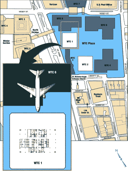 Figure 2-14 Approximate zone of impact of aircraft on the north face of WTC 1.
Neglecting the potential loss of lateral support resulting from collapsed floor slabs and any loss of strength due to elevated temperatures from fires, the most heavily loaded columns were probably near, but not over, their ultimate capacities. Columns located further from the impact zone are thought to have remained substantially below their ultimate capacities. The preliminary analyses also indicate that loss of the columns resulted in some immediate tilting of the structure toward the impact area (extremely unlikely) subjecting the remaining columns and structure to additional stresses from P-delta effects. Also, in part, exterior columns above the zone of impact were converted from compression members to hanger-type tension members, so that, in effect, a portion of the floors' weight became suspended from the outrigger trusses (Figure 2-10) and were transferred back to the interior core columns. The outrigger trusses also would have been capable of transferring some of the load carried by damaged core columns to adjacent core columns. Figure 2-19 illustrates these various secondary load paths. Section 2.2.2.2 provides a more detailed description of these analyses and findings. The above paragraph is mainly nonsense. The building was in fact unlikely to have been stressed any more than it would have been in a hurricane force wind.
 Figure 2-19 Redistribution of load after aircraft impact.
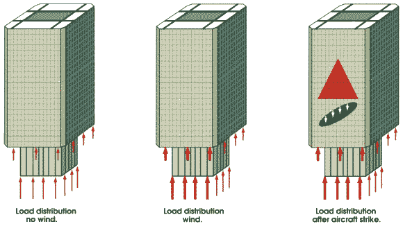
The resulting load distribution after the aircraft impact would have been almost identical to the load distribution incurred by strong wind from the back (i.e., from behind the plane of the page) as in the above graphic. Following the aircraft impact into the building, the structure was able to successfully redistribute the building weight to the remaining elements and to maintain a stable condition. This return to a stable condition is suggested by the preliminary analyses and also evidenced by the fact that the structure remained standing for 1 hour and 43 minutes following the impact. However, the structure's global strength was severely degraded. Although the structure may have been able to remain standing in this weakened condition for an indefinite period, it had limited ability to resist additional loading and could potentially have collapsed as a result of any severe loading event, such as that produced by high winds or earthquakes. WTC 1 probably experienced some additional loading and damage due to the collapse of the adjacent WTC 2. The extent of such damage is not known but likely included broken window and facade elements along the south face. This additional damage was not sufficient to cause collapse. The first event of sufficient severity to cause collapse was the fires that followed the aircraft impact.
At the central zone of impact corresponding to the airplane fuselage and engines, at least five of the prefabricated, three-column sections that formed the exterior walls were broken loose of the structure, and some were pushed inside the building envelope.
Locally, floors supported by these exterior wall sections appear to have partially collapsed, losing their support along the exterior wall. Away from this central zone, in areas impacted by the outer wing structures, the exterior columns were fractured by the force of the collision. Interpretation of photographic evidence suggests that from 31 to 36 columns on the north building face were destroyed over portions of a four-story range. Partial collapse of floors in this zone appear to have occurred over a horizontal length of wall of approximately 65 feet, while floors in other portions of the building appear to have remained intact. Figure 2-16 shows the damage to the exterior columns on the impacted face of WTC 1.
(1) column damage captured from photographs and enchanced video,
(2) Damage to column lines 111-115 at level 96 is estimated.
Figure 2-16 Impact damage to exterior columns on the north face of WTC 1.
In addition to this damage at the building perimeter, a significant but undefined amount of damage also occurred to framing at the central core. For an estimate of the likely damage to the central core (by the University of California, Berkeley professor, Astaneh-Asl) see the article Microsoft Software Used To Simulate The Crash Of A Boeing 747 Into The World Trade Centre. This article claims that the damage caused by the much, much larger and heavier Boeing 747, in a collision with the World Trade Center, would be insufficient to bring the central core down. Interviews were conducted with persons who were present in offices on the 91st floor of the building at the north face of the structure, three floors below the approximate zone of impact. Their descriptions of the damage evident at this floor level immediately following the aircraft impact suggest relatively slight damage at the exterior wall of the building, but progressively greater damage to the south and east. They described extensive building debris in the eastern portion of the central core, preventing their access to the easternmost exit stairway. This suggests the possibility of immediate partial collapse of framing in the central core. These persons also described the presence of debris from collapsed partition walls from upper floors in stairways located further to the west, suggesting the possibility of some structural damage in the northwestern portion of the core framing as well. Figure 2-17 is a sketch made during an interview with building occupants indicating portions of the 91st floor that could not be accessed due to accumulated debris.
It is known that some debris from the aircraft traveled completely through the structure. For example, life jackets and portions of seats from the aircraft were found on the roof of the Bankers Trust building, located to the south of WTC 2. Part of the landing gear from this aircraft was found at the corner of West and Rector Streets, some five blocks south of the WTC complex (Figure 2-18).
As this debris passed through the building, it doubtless caused some level of damage to the structure across the floor plate, including, potentially, interior framing, core columns, framing at the east, south, and west walls, and the floors themselves. The exact extent of this damage will likely never be known with certainty. It is evident that, despite this damage, the structure retained sufficient integrity and strength to remain globally stable for a period of approximately 1 hour and 43 minutes.
The building's structural system, composed of the exterior loadbearing frame, the gravity loadbearing frame at the central core, and the system of deep outrigger trusses in upper stories, was highly redundant. This permitted the building to limit the immediate zone of collapse to the area where several stories of exterior columns were destroyed by the initial impact and, perhaps, to portions of the central core as previously described. Following the impact, floor loads originally supported by the exterior columns in compression were successfully transferred to other load paths. Most of the load supported by the failed columns is believed to have transferred to adjacent perimeter columns through Vierendeel behavior of the exterior wall frame. This is not true. The extra vertical load on the perimeter columns would have distributed itself symmetrically around the perimeter frame (and would not have been concentrated on the adjacent columns). Preliminary structural analyses of similar damage to WTC 2 suggests that axial load demands on columns immediately adjacent to the destroyed columns may have increased by as much as a factor of 6 relative to the load state prior to aircraft impact. However, these exterior columns appear to have had substantial overstrength for gravity loads. Indeed, these exterior columns were designed to resist significant lateral loading and would have had more than sufficient capacity to resist this extra load.
Neglecting the potential loss of lateral support resulting from collapsed floor slabs and any loss of strength due to elevated temperatures from fires, the most heavily loaded columns were probably near, but not over, their ultimate capacities. Columns located further from the impact zone are thought to have remained substantially below their ultimate capacities. The preliminary analyses also indicate that loss of the columns resulted in some immediate tilting of the structure toward the impact area (extremely unlikely) subjecting the remaining columns and structure to additional stresses from P-delta effects. Also, in part, exterior columns above the zone of impact were converted from compression members to hanger-type tension members, so that, in effect, a portion of the floors' weight became suspended from the outrigger trusses (Figure 2-10) and were transferred back to the interior core columns. The outrigger trusses also would have been capable of transferring some of the load carried by damaged core columns to adjacent core columns. Figure 2-19 illustrates these various secondary load paths. Section 2.2.2.2 provides a more detailed description of these analyses and findings. The above paragraph is mainly nonsense. The building was in fact unlikely to have been stressed any more than it would have been in a hurricane force wind.
The resulting load distribution after the aircraft impact would have been almost identical to the load distribution incurred by strong wind from the back (i.e., from behind the plane of the page) as in the above graphic. Following the aircraft impact into the building, the structure was able to successfully redistribute the building weight to the remaining elements and to maintain a stable condition. This return to a stable condition is suggested by the preliminary analyses and also evidenced by the fact that the structure remained standing for 1 hour and 43 minutes following the impact. However, the structure's global strength was severely degraded. Although the structure may have been able to remain standing in this weakened condition for an indefinite period, it had limited ability to resist additional loading and could potentially have collapsed as a result of any severe loading event, such as that produced by high winds or earthquakes. WTC 1 probably experienced some additional loading and damage due to the collapse of the adjacent WTC 2. The extent of such damage is not known but likely included broken window and facade elements along the south face. This additional damage was not sufficient to cause collapse. The first event of sufficient severity to cause collapse was the fires that followed the aircraft impact.
2.2.1.2 Fire Development
It is estimated, based on information compiled from Government sources, that each aircraft contained about 10,000 gallons of jet fuel upon impact into the buildings. A review of photographic and video records show that the aircraft fully entered the buildings prior to any visual evidence of flames at the exteriors of the buildings. This suggests that, as the aircraft crashed into and plowed across the buildings, they distributed jet fuel throughout the impact area to form a flammable «cloud.» Ignition of this cloud resulted in a rapid pressure rise, expelling a fuel rich mixture from the impact area into shafts and through other openings caused by the crashes, resulting in dramatic fireballs.
Although only limited video footage is available that shows the crash of American Airlines Flight 11 into WTC 1 and the ensuing fireballs, extensive video records of the impact of United Airlines Flight 175 into WTC 2 are available. These videos show that three fireballs emanated from WTC 2 on the south, east, and west faces. The fireballs grew slowly, reaching their full size after about 2 seconds. The diameters of the fireballs were greater than 200 feet, exceeding the width of the building. Such fireballs were formed when the expelled jet fuel dispersed and flames traveled through the resulting fuel/air mixture. Experimentally based correlations for similar fireballs (Zalosh 1995) were used to estimate the amount of fuel consumed. The precise size of the fireballs and their exact shapes are not well defined; therefore, there is some uncertainty associated with estimates of the amount of fuel consumed by these effects. Calculations indicate that between 1,000 and 3,000 gallons of jet fuel were likely consumed in this manner. Barring additional information, it is reasonable to assume that an approximately similar amount of jet fuel was consumed by fireballs as the aircraft struck WTC 1.
Although dramatic, these fireballs did not explode or generate a shock wave. If an explosion or detonation had occurred, the expansion of the burning gasses would have taken place in microseconds, not the 2 seconds observed. Therefore, although there were some overpressures, it is unlikely that the fireballs, being external to the buildings, would have resulted in significant structural damage. It is not known whether the windows that were broken shortly after impact were broken by these external overpressures, overpressures internal to the building, the heat of the fire, or flying debris.
The first arriving firefighters observed that the windows of WTC 1 were broken out at the Concourse level. This breakage was most likely caused by overpressure in the elevator shafts. Damage to the walls of the elevator shafts was also observed as low as the 23rd floor, presumably as a result of the overpressures developed by the burning of the vapor cloud on the impact floors.
If one assumes that approximately 3,000 gallons of fuel were consumed in the initial fireballs, then the remainder either escaped the impact floors in the manners described above or was consumed by the fire on the impact floors. If half flowed away, then approximately 4,000 gallons remained on the impact floors to be consumed in the fires that followed. The jet fuel in the aerosol would have burned out as fast as the flame could spread through it, igniting almost every combustible on the floors involved. Fuel that fell to the floor and did not flow out of the building would have burned as a pool or spill fire at the point where it came to rest.
The time to consume the jet fuel can be reasonably computed. At the upper bound, if one assumes that all 10,000 gallons of fuel were evenly spread across a single building floor, it would form a pool that would be consumed by fire in less than 5 minutes (SFPE 1995) provided sufficient air for combustion was available. In reality, the jet fuel would have been distributed over multiple floors, and some would have been transported to other locations. Some would have been absorbed by carpeting or other furnishings, consumed in the flash fire in the aerosol, expelled and consumed externally in the fireballs, or flowed away from the fire floors. Accounting for these factors, it is believed that almost all of the jet fuel that remained on the impact floors was consumed in the first few minutes of the fire.
As the jet fuel burned, the resulting heat ignited office contents throughout a major portion of several of the impact floors, as well as combustible material within the aircraft itself.
A limited amount of physical evidence about the fires is available in the form of videos and still photographs of the buildings and the smoke plume generated soon after the initial attack. Estimates of the buoyant energy in the plume were obtained by plotting the rise of the smoke plume, which is governed by buoyancy in the vertical direction and by the wind in the horizontal direction. Using the Computational Fluid Dynamics (CFD) fire model, Fire Dynamics Simulator Ver. 1 (FDS1), fire scientists at the National Institute of Standards and Technology (NIST) (Rehm, et al. 2002) were able to mathematically approximate the size of fires required to produce such a smoke plume. As input to this model, an estimate of the openings available to provide ventilation for the fires was obtained from an examination of photographs taken of the damaged tower. Meteorological data on wind velocity and atmospheric temperatures were provided by the National Oceanic and Atmospheric Administration (NOAA) based on reports from the Aircraft Communications Addressing and Reporting System (ACARS). The information used weather monitoring instruments onboard three aircraft that departed from LaGuardia and Newark airports between 7:15 a.m. and 9:00 a.m. on September 11, 2001. The wind speed at heights equal to the upper stories of the towers was in the range of 10-20 mph. The outside temperatures over the height of the building were 20-21 degrees Centigrade (68-70 degrees Fahrenheit).
The modeling suggests a peak total rate of fire energy output on the order of 3-5 trillion Btu/hr, around 1-1.5 gigawatts (GW), for each of the two towers. From one third to one half of this energy flowed out of the structures. This vented energy was the force that drove the external smoke plume. The vented energy and accompanying smoke from both towers combined into a single plume. The energy output from each of the two buildings is similar to the power output of a commercial power generating station (this is the same type of misleading statement that the «Scientific» American article made, in its description of the aircraft strikes and fires in the WTC as equivalent to small nuclear weapons going off). The modeling also suggests ceiling gas temperatures of 1,000 degrees Centigrade (1,800 degrees Fahrenheit), for all of 5 minutes, until the jet-fuel burnt off, with an estimated confidence of plus or minus 100 degrees Centigrade (200 degrees Fahrenheit) or about 900-1,100 degrees Centigrade (1,600-2,000 degrees Fahrenheit).